





Packaging machine installation planning should begin with the exact equipment configuration and current installation information, then move through delivery access, usable operating and service space, utility interfaces, production-line handoffs, responsibility ownership, and schedule dependencies. The installation date should be treated as the result of those prerequisites being ready—not as the starting assumption.
This matters because a machine can fit on a floor plan and still be difficult to install or operate. The delivery route may be restricted, feeder or discharge areas may need more space than the nominal machine footprint suggests, a facility utility may exist but not match the selected configuration, or a critical site task may have no clearly assigned owner. Any one of those gaps can keep the project from being genuinely installation-ready.
For HORDA-manufactured equipment, the supplied manufacturer catalogue shows why installation planning should remain configuration-specific. HORDA notes on its production-line solutions that the particular plan, including site and operator arrangements, is developed according to the customer’s actual requirements. The same catalogue documents different physical arrangements and model-specific dimensions, power and weight across integrated lines and standalone machines, so one model’s requirements should not be transferred to another without current applicable documentation.
The practical objective is therefore not to create a generic “machine installation checklist.” It is to build a traceable readiness record for the actual machine, facility and project. This page focuses on coordinating pre-installation readiness; detailed utility design, rigging methods and commissioning acceptance still require their own project-specific review.
What Must Be Confirmed Before the Packaging Machine Arrives?
Start by establishing exactly what is being installed. A project cannot reliably finalize utilities, access, layout or installation timing while the equipment identity or configuration is still ambiguous.
The baseline should identify the selected model, any connected modules or line configuration, the current arrangement or installation documentation available for that equipment, and the revision of the documents being used. If a machine is part of an integrated line, the planning basis should describe the connected arrangement rather than treating each module as an independent rectangle on a floor plan.
That distinction is particularly important for packaging machinery because process interfaces can be part of the physical installation problem. HORDA’s integrated case-making and inner-lining arrangements, for example, show multiple feeding, conveying, folding, lining and collection functions in one production route rather than a single isolated workstation.
A useful installation-input register can look like this:
| Installation input | What to confirm | Evidence to use |
|---|---|---|
| Equipment identity | Exact model and configuration | Order, approved equipment list, current manufacturer data |
| Arrangement | Standalone machine or connected line | Current layout / GA / installation drawing where available |
| Transport condition | How the equipment is delivered and moved | Packing or shipment information where supplied |
| Utilities | Applicable electrical and other connections | Exact-machine technical documentation |
| Process interfaces | Infeed, outfeed and adjacent equipment | Production-line layout and process plan |
| Responsibility | Who provides each prerequisite | Contract, quotation, project responsibility matrix |
| Schedule basis | Which conditions must close before installation | Project plan and readiness record |
HORDA’s catalogue also warns that machine structures and technical parameters may change, which is another reason to confirm the current applicable information rather than relying indefinitely on an older catalogue value.
Can the Machine Reach the Intended Installation Position?
The first physical-layout question is not “Does the machine fit where we want it?” It is “Can the actual equipment reach that position safely?”
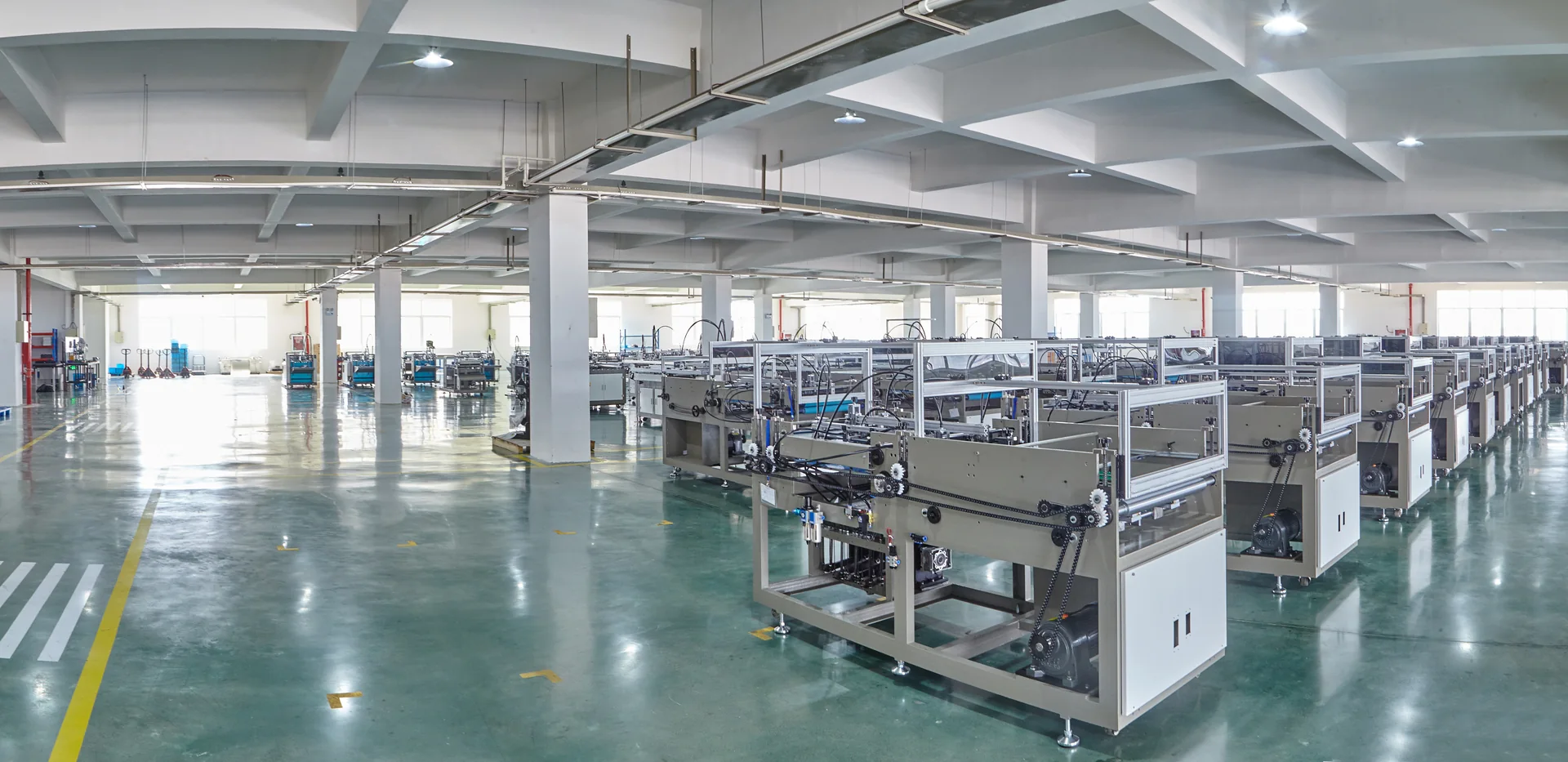
A final installation location may have sufficient floor area while the route to it has a doorway, turn, corridor, loading area or obstruction that makes the move more difficult. Transport or packed dimensions may also differ from the final installed condition. For that reason, delivery-to-position feasibility should be checked independently from the final layout.
Walk the real route rather than relying only on a general building drawing. Measure the relevant entrances and passages, identify turns or height restrictions, locate floor transitions and obstructions, and confirm where unloading ends and internal movement begins. The dimensions and mass used for that review should come from the applicable equipment or shipment information rather than from a visually similar model.
The handling method matters as well. A route that works for one load and handling arrangement may not work for another. This article should not be used to select a forklift, crane, lifting point or rigging method; those decisions require the actual load information and competent handling planning.
Floor conditions belong in the same feasibility check. Where machine or handling loads make floor capacity relevant, the site team should compare the expected machine and handling loads with the applicable building or floor information and obtain qualified structural review where needed. A generic packaging-machine article cannot determine slab capacity, foundation design or anchoring requirements.
For U.S. workplaces, OSHA requires sufficient safe clearances where mechanical handling equipment moves through aisles, loading docks, doorways, turns and passages, and requires walking-working surfaces to support the maximum intended load. These requirements support route and floor-load checks, but they do not provide a universal machine-clearance or foundation value for a specific project. See OSHA 29 CFR 1910.176 and 29 CFR 1910.22.
The decision at the end of this review is simple: either the real equipment can be moved to the intended location under an appropriate handling plan, or the access issue needs to be resolved before delivery and positioning are treated as ready.
Plan the Layout Around Operation, Service and Material Flow
A machine’s published external dimensions are a starting point for layout planning, not the entire operating envelope.
Packaging machinery normally interacts with materials before and after the main process. Depending on the selected configuration, the project may need space for board or paper feeding, finished-product discharge, collection, operator movement, material staging, electrical access, tooling or maintenance access, and an upstream or downstream machine interface.
This is why two layouts with the same nominal machine footprint can perform very differently in practice. One may allow the machine body to fit but leave no practical area to load material. Another may preserve infeed space but interfere with access to an electrical cabinet or service point. A connected production line adds another layer: the relative position and transfer direction of modules can matter as much as their individual external dimensions.
HORDA’s published diagrams illustrate this configuration effect. Documented integrated case-making and inner-lining arrangements include feeding, gluing, folding, overturning, inner-paper handling and collection functions, while other catalogue configurations show their own feeding, cabinet and collection arrangements. Those examples are useful for understanding the planning principle, but they do not establish universal clearance distances.
A practical layout review should distinguish the following interfaces:
| Layout interface | Question to answer before approval |
|---|---|
| Machine body | Does the selected configuration fit the proposed position? |
| Infeed/loading | Can operators and materials reach the feeding point as intended? |
| Outfeed/collection | Is there enough room to receive and remove finished work? |
| Service/electrical access | Can required access points be reached without creating a conflict? |
| Operator movement | Does the proposed arrangement support normal operating tasks? |
| Material staging | Where will incoming and outgoing material wait? |
| Upstream/downstream handoff | Do connected processes align physically and operationally? |
| Future movement | Could routine service or planned changeover activity be obstructed? |
Do not turn this matrix into a set of universal distances. The correct dimensions depend on the selected machine, configuration, site and applicable documentation.
Verify Utility and Environmental Interfaces
A facility having electricity, compressed air or other services available does not mean those services are automatically suitable for the selected machine.
Utility planning should therefore be performed as a comparison between two sides: the documented requirement of the selected equipment and the actual condition available at the installation point.
For the electrical interface, confirm the applicable supply characteristics, machine power information, connection method and connection location from current equipment documentation. The facility side should then be reviewed by appropriately qualified personnel for compatibility, protection, grounding and the applicable site requirements. For U.S. workplaces, OSHA also requires sufficient access and working space around electrical equipment for safe operation and maintenance; this is an electrical-safety requirement, not a universal machine service-clearance value. See OSHA 29 CFR 1910.303.
Other interfaces should be treated the same way. If the selected equipment requires compressed air, a process connection, adhesive-related provision or particular environmental conditions, verify those requirements for the exact configuration rather than borrowing a number from another machine.
HORDA’s catalogue illustrates why model identity matters: documented power and physical values differ among machines and integrated configurations. The useful lesson is not any single catalogue number. It is that utility assumptions should remain tied to the actual equipment.
Use a utility interface record such as:
| Interface | Machine-side requirement | Site condition | Status / action |
|---|---|---|---|
| Electrical supply | Confirm voltage, frequency, phase and stated power requirement for the exact configuration | Confirm facility supply and intended connection point | Match / resolve |
| Electrical connection | From applicable documentation | Confirm protective devices, grounding and site work as applicable | Ready / open |
| Compressed air, if applicable | Confirm the exact machine requirement | Confirm available pressure, flow and connection condition | Ready / open |
| Process/glue utility, if applicable | Configuration-specific requirement | Confirm site provision | Ready / open |
| Environment, where specified | Documented applicable condition | Verify installation area | Accept / resolve |
The table should contain actual project data before it is used as an installation release record.
Define Responsibility Before the Installation Date Is Set
Many installation problems are not caused by an unknown technical requirement. They are caused by a known task with no clearly assigned owner.
For example, a project team may know that a power connection is needed but have different assumptions about who supplies the cable, disconnect, final connection or inspection. The machine may need to be moved from the unloading point to the production floor, but the order may not automatically place that work in the machinery supplier’s scope. The same ambiguity can affect site preparation, specialist contractors, commissioning and training.
The solution is to separate what must happen from who is contractually responsible for making it happen.
A responsibility matrix should be built from the actual quotation, purchase order, technical agreement and project plan rather than from assumptions about what a manufacturer, dealer or buyer “usually” provides. ANSI/PMMI B155.1-2023 also identifies responsibilities among packaging-machinery suppliers, users, modifiers and other stakeholders as part of machinery safety, but it does not determine the commercial scope of a particular order.
| Prerequisite | Responsible party | Required evidence | Due point |
|---|---|---|---|
| Site access prepared | Project-defined owner | Route/site confirmation | Before equipment movement |
| Utility supply available | Project-defined owner | Facility verification | Before connection |
| Machine-side documents available | Project-defined owner | Current applicable documents | Before final site preparation |
| Handling arrangement | Project-defined owner | Approved handling plan as applicable | Before unloading/positioning |
| Installation work scope | Project-defined owner | Contract/order scope | Before scheduling personnel |
| Commissioning handoff | Project-defined owner | Installation prerequisites complete | After installation stage |
The labels “project-defined owner” are deliberate. Without the actual commercial documents, it would be unsafe to state that a particular party automatically owns unloading, wiring, installation labor, travel, commissioning or training.
This separation also prevents a common project-management error: booking technical personnel or setting an installation date while critical buyer-side or contractor-side prerequisites remain unassigned.
Build the Installation Timeline From Dependencies, Not From a Date
A useful installation timeline is a dependency model, not a generic promise that a machine will be installed in a fixed number of days.
Start with the intended installation milestone and work backward. What has to be true before the equipment can be moved into position? What must be complete before utilities can be connected? What documentation or personnel must be available before the next task starts? Which unresolved condition would stop the sequence?
That produces a schedule based on predecessor conditions:
| Milestone | Predecessor condition | Evidence of readiness |
|---|---|---|
| Site released for delivery | Access and installation area prepared | Site/readiness review |
| Equipment moved to position | Handling route and method ready | Route and handling confirmation |
| Utility connection starts | Machine location fixed and site services prepared | Utility/interface check |
| Installation stage closes | Required installation work completed | Project-defined completion record |
| Commissioning can begin | Commissioning prerequisites available | Handoff review |
This approach makes schedule risk visible earlier. If the installation date depends on a facility modification, document release or contractor task that is still open, the project team can see that dependency instead of discovering it after the machinery arrives.
It also keeps installation and commissioning separate. Physical placement and connection may be prerequisites for commissioning, but they do not by themselves prove stable production, operator readiness or final performance acceptance. Those downstream tasks need their own criteria.
The actual duration of each stage remains project-specific. Machine configuration, site complexity, handling arrangements, local work scope and personnel availability can all change the sequence. A planning guide can provide the logic for scheduling; it should not invent an installation-duration benchmark.
Common Installation Planning Mistakes That Cause Project Risk
The most useful “common mistakes” are not anecdotes. They are planning assumptions that can be tested before machinery arrives.
| Planning mistake | Why it creates risk | Early check |
|---|---|---|
| Using the machine footprint as the whole space requirement | Ignores loading, discharge, operator and service interfaces | Review the usable operating envelope |
| Measuring only the final installation area | The equipment may not pass through the actual route | Survey the full delivery-to-position path |
| Assuming an existing utility is suitable | Supply characteristics may not match the selected configuration | Compare exact requirements with real site conditions |
| Planning each machine independently in a connected line | Transfer direction and adjacent processes may conflict | Review interfaces as one production route |
| Leaving tasks under “supplier/buyer to confirm” | No one owns the prerequisite or deadline | Assign one project owner and evidence requirement |
| Fixing the installation date before prerequisites close | Open dependencies remain hidden behind the calendar | Use milestone readiness gates |
The objective is not to predict exactly how much delay any mistake will cause. Without project records, that would be speculation. The objective is to identify the missing evidence while the project still has time to resolve it.
Pre-Installation Readiness Checklist: Go or No-Go?
The final planning step is to convert the preceding reviews into a documented readiness decision.
A useful checklist should not merely ask “Is the site ready?” It should show what requirement was checked, what evidence supports the answer, who owns any open action, and whether the issue prevents the next installation activity.
| Readiness item | Evidence / verification | Status |
|---|---|---|
| Exact machine/configuration confirmed | Current equipment/order data | Ready / open |
| Current applicable technical documents available | Drawing/manual/data revision checked | Ready / open |
| Delivery-to-position route checked | Actual route measurements/review | Ready / open |
| Installation location and usable layout reviewed | Layout including operating/service interfaces | Ready / open |
| Applicable utilities checked | Machine requirement compared with site condition | Ready / open |
| Adjacent process interfaces resolved | Upstream/downstream arrangement reviewed | Ready / open |
| Handling responsibility defined | Project scope / approved arrangement | Ready / open |
| Site/utility work ownership assigned | Responsibility matrix | Ready / open |
| Required personnel/contractors scheduled | Project plan | Ready / open |
| Installation prerequisites complete | Evidence attached or recorded | Ready / blocker |
For internal project control, the team can classify a condition as ready, open-but-nonblocking, or blocking according to its actual project rules. Those labels should not be mistaken for manufacturer certification, regulatory approval, FAT, SAT or commissioning acceptance.
A “no-go” decision at this stage is not necessarily a project failure. It is often the correct outcome when a prerequisite has not been verified. Discovering the gap before the machine is positioned is more useful than hiding it behind a planned date.
When you are preparing an installation-readiness review or quotation, gather the exact machine/configuration, current site or layout drawing, delivery-access constraints, available utility information, adjacent equipment interfaces, proposed installation period, and the installation/support scope you expect. If you want Raymon Machinery to review those inputs for a HORDA equipment inquiry, send the project requirements through the current inquiry channel. The supplying party and installation, commissioning, training and after-sales responsibilities should still be confirmed in the written quotation and order.