Independent equipment channel featuring HORDA machineryCase making · inner lining · collapsible boxes · frame stretching
Menu
Home / Technical guide
Technical guide

CCD and photoelectric positioning

CCD and photoelectric positioning. Control the material and process variables that affect repeatable accepted output.

Evidence-gated draft: technical facts, images and application proof require review before search indexing.
Technical guide review

Define what ccd and photoelectric positioning must achieve.

A CCD vs photoelectric positioning case making decision starts with the real product, complete format range, material specification, accepted-output target and the operation that receives the result.

Discuss this requirement →

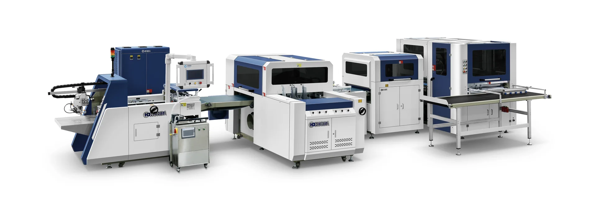
HORDA ZFM-700F/1000F automatic case making machine
Supplied visual evidence

Equipment and process references

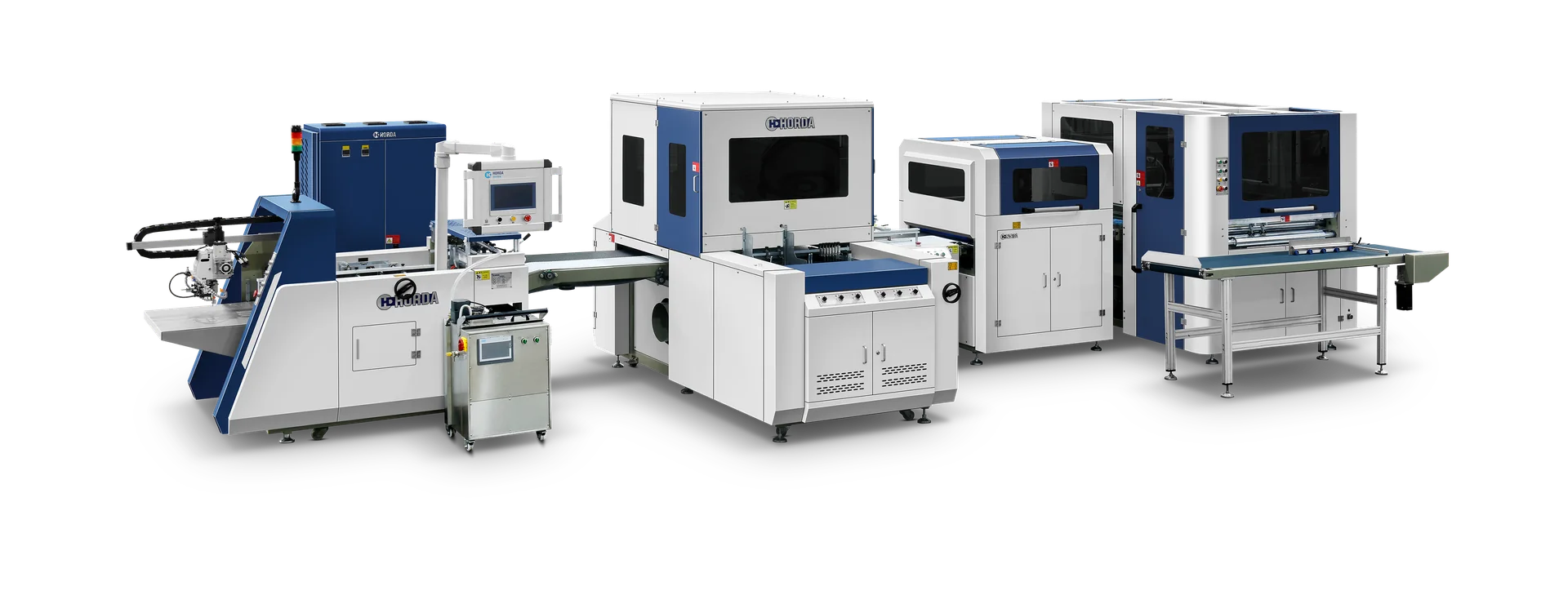
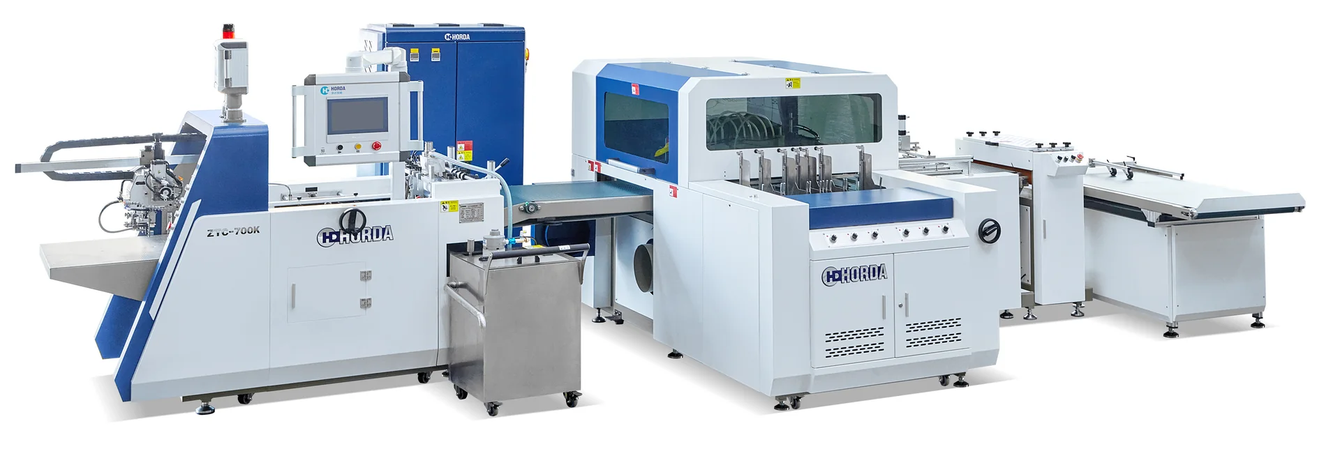
These supplied equipment images support process discussion. Confirm the exact model revision, guarding, options and configuration in the current written offer.

HORDA ZFM-700F/1000F automatic case making machine
HORDA ZFM-700E/1000E automatic case making machine
HORDA ZTC-700 automatic inner laminating machine

Image source: materials supplied for this project. Product, machine and facility identity must be confirmed against the current quotation before making a contractual claim.

Technical control plan

Match the sensor to the artwork—not to a marketing label.

Photoelectric correction and CCD positioning need different detectable features, setup methods and evidence. Compare them on the same printed job.

01Define registrationName the artwork and board checkpoints that control acceptance.
02Inspect the printConfirm contrast, marks, repeated patterns and print-to-cut variation.
03Select the sensing methodUse photoelectric correction for suitable marks or CCD for visual feature location.
04Run equal-condition trialsKeep materials, layout and inspection tools consistent.
05Compare measured resultsReview deviation, setup time, waste and accepted output.

Variables that change the equipment decision

  • Detectable marks or visual features
  • Required registration checkpoints
  • Artwork changes across the job mix
  • Setup skill, waste and accepted output
Scope boundary: Published positioning accuracy is not a complete finished-product tolerance because printing, cutting, material stretch and measurement method contribute error.
Decision framework

Three checks for ccd and photoelectric positioning.

Use these checks to keep the CCD vs photoelectric positioning case making discussion tied to measurable inputs, outputs and responsibility boundaries.

Controlled variable

Define how ccd and photoelectric positioning is measured during a repeatable production trial.

Reference sample

Compare changes related to CCD vs photoelectric positioning case making against one approved physical result.

Recorded outcome

Document settings, defects and accepted output when evaluating ccd and photoelectric positioning.

Information for review

Prepare a complete CCD vs photoelectric positioning case making brief.

The six items below reduce assumptions when evaluating ccd and photoelectric positioning and make competing technical offers easier to compare.

Variable definitionRecord this item specifically for ccd and photoelectric positioning rather than relying on a generic machine request.
Measurement methodGive the minimum, maximum or current condition that applies to the ccd and photoelectric positioning project.
Reference sampleAttach a drawing, photograph, specification or physical sample relevant to ccd and photoelectric positioning.
Trial conditionsState how this ccd and photoelectric positioning requirement will be inspected and accepted.
Defect recordExplain present production, job mix and the expected change connected with ccd and photoelectric positioning.
Corrective actionConfirm who supplies, approves and supports this part of the ccd and photoelectric positioning scope.
Project sequence

Move ccd and photoelectric positioning from sample to written scope.

Keep the same product definition, material set and acceptance method throughout the CCD vs photoelectric positioning case making trial, quotation and order.

01Define the variable for CCD and photoelectric positioning
02Keep an approved reference for CCD and photoelectric positioning
03Measure current conditions for CCD and photoelectric positioning
04Change one factor for CCD and photoelectric positioning
05Record the result for CCD and photoelectric positioning
Frequently asked questions

Questions about ccd and photoelectric positioning.

Use the answers as a starting checklist and confirm project-specific statements with current technical evidence.

Why does ccd and photoelectric positioning matter?

It can change feeding stability, registration, wrapping quality, repeatability or the acceptance result for the finished component.

Can a catalogue value replace a sample trial?

No. Catalogue values screen the project; actual materials and an agreed inspection method determine practical fit.

Which variables should be recorded?

Record material specification, flat dimensions, machine settings, ambient conditions, defects, accepted output and the approved reference sample.

How should a process change be evaluated?

Change one controlled variable at a time and compare the result against the same approved sample and inspection criteria.

Primary topic: CCD vs photoelectric positioning case making. This page remains excluded from search while its facts, images and application proof are under review.

Explore next

Related planning pages.

Continue from ccd and photoelectric positioning to the most relevant equipment, process, application or buyer-information page.

Build the right process

Ready to review your box sample?

Send the finished product, flat drawing, materials, size range and target output.

Request a quote →