
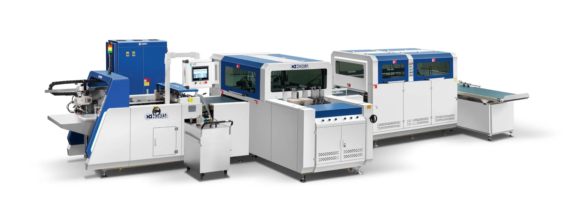
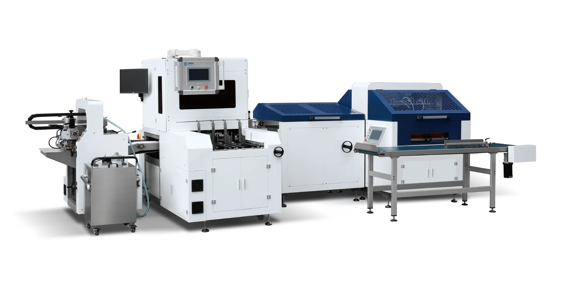
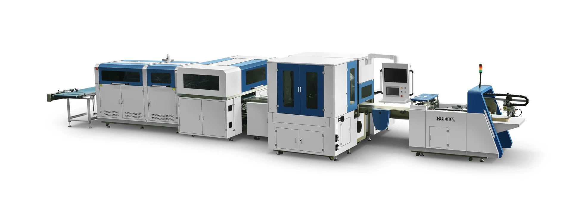
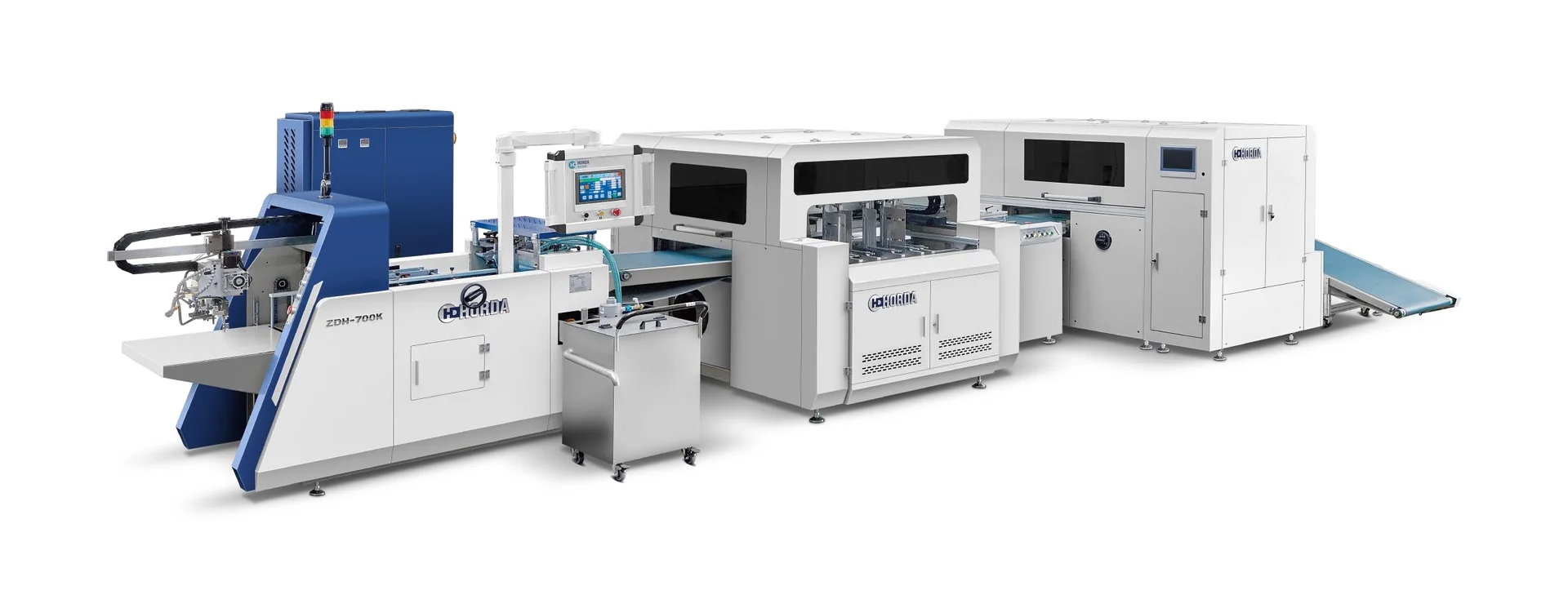
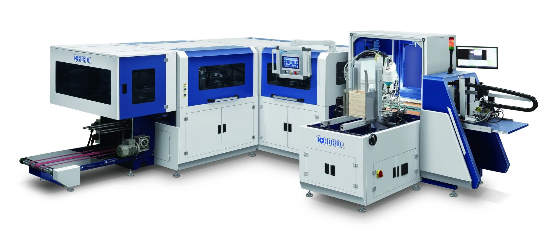
Choosing eyewear presentation box making equipment starts with the box structure, not the machine model. A rigid presentation box for sunglasses or optical frames may require board cutting, printed-paper wrapping, rigid box forming, inner lining, a protective insert, and final assembly. These operations are not necessarily performed by one machine.
For a book-style eyewear presentation box, an automatic case maker can produce the wrapped outer cover, while a separate forming station produces the internal tray. Lining and insert-fitting operations then complete the package. A two-piece lid-and-base box follows a different forming route. A collapsible presentation box may require specialized cover and side-wing equipment.
The practical selection rule is to define the finished package, identify every component, and match each operation to a machine or production station. Flat component dimensions, board thickness, covering-paper properties, adhesive compatibility, insert geometry, and required good output determine whether the proposed line is suitable.
Choose the Eyewear Box Structure Before Selecting Equipment
Eyewear packaging presents a specific engineering challenge: the product is relatively light, but the lenses, frame finish, bridge, and hinges can be sensitive to contact pressure and abrasion. The box therefore needs an acceptable external appearance and an internal structure that holds the eyewear without damaging it.

Before selecting machinery, measure the eyewear with its temples folded and identify the intended orientation inside the package. Check the widest frame, overall folded thickness, bridge height, and any accessories such as a cleaning cloth or protective pouch. The relevant dimensions are the maximum product envelope and the required internal clearance, not simply the manufacturer’s nominal frame width.
Several rigid packaging structures are relevant, and each leads to a different equipment route.
Book-Style Rigid Presentation Boxes
A book-style box uses a wrapped outer case with two panels connected by a spine or hinge area. An internal rigid tray or formed compartment holds the eyewear. The closure may use magnets, a ribbon, or another mechanism.
This structure is a logical candidate for automatic hardcover case making because the outer cover resembles a multi-board hardcover case. However, producing that wrapped case does not automatically form the internal tray, install magnets, fit the insert, or assemble the completed box.
Book-style construction is worth evaluating when a premium opening experience, printed exterior, and separate protective compartment are required. The hinge geometry and tray height must be tested together: a correctly wrapped cover can still fail to close if the tray, insert, or eyewear projects into the lid’s closing path.
Two-Piece Lid-and-Base Rigid Boxes
A lift-off lid and base use separate rigid box components rather than a continuous book-style case. Production generally involves preparing board blanks, forming the box structures, wrapping their exterior surfaces, and fitting the internal presentation components.
The required equipment therefore emphasizes rigid box forming and wrapping. An automatic hardcover case maker should not be assumed to perform the complete lid-and-base forming operation merely because both processes use greyboard and covering paper.
For this design, buyers should specify the finished internal cavity, wall height, lid engagement, and opening resistance. Excessively tight engagement can damage the wrapped corners or make the package difficult to open, while loose engagement may compromise presentation quality.
Drawer and Collapsible Presentation Boxes
Drawer-style packaging requires a sleeve and a sliding tray, with particular attention to sliding clearance and friction between finished surfaces. Collapsible rigid boxes introduce folding joints, side wings, and additional assembly operations.
These structures may justify specialized equipment, but they should not be grouped automatically with conventional hardcover case making. A collapsible-wing machine produces a particular component; it does not necessarily assemble a complete eyewear gift box.
For a new project, select the box structure using an approved physical sample before deciding whether a dedicated forming line, a case-making line, or a combination of machines is appropriate.
Map the Production Process From Board Cutting to Final Assembly
A workable eyewear presentation box production setup separates material preparation, component manufacturing, and finished-box assembly. The process below describes a representative book-style rigid presentation box. Actual station arrangements depend on the approved construction and equipment configuration.
- Structural design and material preparation: Prepare flat drawings for the outer case, internal tray, covering paper, lining, and insert. Define each component’s dimensions, material, grain direction where relevant, and assembly relationship.
- Board slitting and die-cutting: Cut greyboard into accurately sized panels. Die-cut or otherwise profile components that require shaped corners, openings, or special contours. Prepare the printed covering sheets and insert blanks separately.
- Outer case making: Feed the board and covering paper, apply adhesive, register the components, and wrap the covering paper around the board edges.
- Rigid tray or box-body forming: Form the internal compartment that will support the eyewear insert. This may require equipment separate from the hardcover case maker.
- Inner lining and insert assembly: Apply lining paper where specified, prepare the protective insert, and install it inside the formed tray. Add closure hardware or other components according to the box design.
- Final assembly and inspection: Join the relevant box components, inspect appearance and dimensions, verify eyewear fit, and count accepted finished boxes.
The key purchasing distinction is between a machine’s output component and the finished retail package. A station producing 20 wrapped cases per minute does not establish that the complete eyewear packaging line produces 20 accepted boxes per minute.
Die-Cutting and Board Preparation: Control the Flat Geometry
Die-cutting quality affects far more than the appearance of the initial blank. Errors introduced during cutting can carry through registration, wrapping, tray assembly, and final closure.
For straight rectangular greyboard pieces, precision board slitting or cutting may be sufficient. Die-cutting becomes more relevant when the design includes shaped edges, special corner reliefs, cutouts, or profiled insert components. Printed cover sheets may also require die-cutting or trimming to their own developed dimensions.
The appropriate cutting technology depends on material thickness, part geometry, tooling requirements, batch size, and cutting quality. For example, a digital cutting table may be useful for design verification and short-run prototypes, while a suitable die-cutting process may be more economical for repeated production with stable geometry.
BOBST’s technical overview of carton converting explains how substrate properties, die-cutting, and creasing influence converting operations. Its discussion provides useful cutting-process principles, although a rigid greyboard case must still be evaluated against its own materials and tooling requirements.
Why Finished Box Dimensions Are Not Enough
A hardcover case-making machine processes a flat arrangement of board components and covering material. Its working-format limits cannot be evaluated from the closed box dimensions alone.
Consider a hypothetical book-style eyewear box design with the following flat board arrangement:
- Two outer panels, each 180 mm wide and 90 mm high.
- One spine panel, 36 mm wide and 90 mm high.
- Two hinge gaps, each 3 mm wide.
- A proposed covering-paper turn-in allowance of 12 mm around the outside perimeter.
Illustrative hypothetical calculation: If the panels and hinge gaps are arranged along the same width, the overall board-layout width is 180 + 36 + 180 + (2 × 3) = 402 mm. The board-layout height is 90 mm.
With the stated turn-in allowance, the initial nominal covering-paper blank would be approximately 426 × 114 mm before any additional trimming, printing-registration allowance, corner treatment, or process-specific correction.
This is a geometric illustration, not a verified HORDA working format or a validated hinge design. The actual hinge gaps and turn-in allowances must be tested against board thickness, covering material, folding geometry, and the required opening behavior. The machine supplier must also confirm which dimensions its published working range refers to.
The 90 mm short side in this example is particularly important when screening equipment. HORDA’s supplied 2026 catalogue lists a 90 × 180 mm minimum product size for the ZFM-700K, but a 140 × 240 mm minimum for the ZFM-1000K. These are catalogue screening values, not proof that either machine will handle this particular board arrangement or covering-paper blank. Feeding orientation, the actual format definition, and a trial with the intended materials must decide compatibility.
For equipment selection, provide both the board arrangement and the complete covering-paper blank. Check the minimum and maximum format, smallest individual board width, board count, feeding orientation, corner geometry, and any tooling or positioning constraints.
Control Cutting Quality at the Source
Unequal board panels can create visible asymmetry even when the case maker positions the entire layout correctly. Inconsistent cut lengths can produce unequal wrapping margins. Rough or crushed board edges may become visible beneath thin covering materials.
Inspect the cut components before introducing them into the wrapping process. Measure representative pieces, check for edge damage, and confirm that printed artwork and structural cutting references correspond to the same approved drawing.
Structural packaging design software can assist with the relationship between cut lines, fold geometry, and assembled structures. Esko’s ArtiosCAD documentation describes the use of structural design, 2D/3D development, and internal fitment design to identify potential production issues before manufacturing.
Case Making Equipment: What HORDA Machines Actually Produce
HORDA’s case-making equipment is relevant to eyewear presentation boxes when the design includes a wrapped hardcover-style outer component. The manufacturer’s supplied equipment catalogue distinguishes automatic case making from inner laminating, rigid box forming, and subsequent assembly operations.
ZFM Automatic Case Making Machines
The HORDA ZFM-700/1000K series is designed for automatic hardcover case making. Its documented workflow includes board feeding, covering-paper feeding, gluing, photoelectric registration with servo correction, and four-side edge wrapping.
For a book-style eyewear presentation box, this equipment may be considered for the outer case if the flat dimensions, board arrangement, covering material, and required edge quality are compatible.
The two formats should be compared using the project’s complete minimum and maximum flat layouts. A larger-format model is not automatically preferable for small eyewear packaging: minimum feeding dimensions, individual board widths, changeover requirements, and production space must also be considered. In HORDA’s supplied 2026 catalogue, the ZFM-700K maximum product size is 450 × 720 mm, compared with 600 × 1050 mm for the ZFM-1000K. Confirm the size definition and current quotation revision rather than interpreting these figures as finished-box cavity dimensions.
The HORDA ZFM-700/1000K equipment overview provides the manufacturer’s catalogue-based case-making process and model comparison. Published working ranges and nominal speeds are screening information, not guaranteed results for every eyewear box design.
Where the presentation box requires rounded outer corners, HORDA’s ZFM-500B round-corner case-making category may warrant examination. The required corner radius, covering-paper relief, and finished appearance must be confirmed using the actual sample rather than assumed from the machine’s general description.
Combined Case Making and Inner Laminating
For a design requiring inner paper laminated onto the wrapped outer case, a linked case-making and inner-laminating system may reduce intermediate handling.
HORDA’s QZFM case-making and inner-laminating equipment combines cover production, case transfer, and lining-paper application. Its documented operations include board and paper feeding, gluing, case wrapping, transferring or turning the case, inner-paper feeding, positioning, and laminating. The supplied catalogue describes QZFM-700/1000K configurations; separately published HORDA materials also describe QZFM-A configurations. Those model identities and specifications must not be treated as interchangeable.
However, inner laminating means applying lining material to a prepared case surface. It should not be confused with cutting an eyewear-shaped foam insert, forming a rigid compartment, or placing the eyewear into the box.
Standalone HORDA ZTC inner-laminating machines are another potential option where the outer case is manufactured separately. The decision between linked and standalone equipment depends on format compatibility, production volume, scheduling flexibility, and the balance between case-making and lining capacity.
Current model versions, positioning arrangements, material ranges, and included modules must be checked against the applicable manufacturer’s documentation and written quotation. Features from different HORDA models should not be combined into a single assumed configuration.
When a Case Maker Is Not the Right Main Machine
A conventional two-piece rigid eyewear box may need dedicated lid-and-base forming and wrapping equipment rather than a hardcover case-making station. Likewise, a collapsible design may need specific side-wing production machinery.
HORDA’s DFM multifunction cover and wing equipment and ZDH wing-making equipment belong to different process categories. They should only enter the shortlist when the approved eyewear box structure actually requires those components. They should not be represented as complete eyewear box assembly machines.
The machinery proposal should identify the exact input and output of every station. This prevents the frequent procurement error of purchasing equipment that makes an attractive outer component but leaves essential downstream operations unprovided.
Gluing and Wrapping: Material Compatibility Determines Appearance
The exterior of an eyewear presentation box is often the most visible quality feature. Printed logos, matte or gloss finishes, embossed details, and accurately wrapped corners can expose small deviations that would be less noticeable on ordinary transport packaging.
The mechanical performance of wrapping depends on interactions among the covering sheet, board, adhesive, and handling conditions.
Separate Paper Grammage From Board Thickness
Covering-paper grammage is normally specified as mass per unit area in g/m², or gsm. Greyboard thickness is specified in millimeters. These quantities describe different material properties and cannot be substituted for one another.
Two papers with the same grammage may behave differently because of coating, fiber composition, grain direction, and surface treatment. Likewise, two boards with the same nominal thickness may differ in stiffness, moisture behavior, and edge quality.
The supplier should therefore evaluate actual covering-paper and board samples rather than approve a material solely because its nominal number falls within a catalogue range.
Adhesive Selection and Open Time
During case wrapping, adhesive must remain suitable for bonding while the covering paper is positioned, folded, and pressed against the board. If the adhesive loses workable tack before the wrapping operation is completed, edge lifting or weak bonding may result.
Excess adhesive or unsuitable application conditions can produce staining, surface distortion, squeeze-out, or uneven appearance. Poor wetting of a coated surface can also lead to delamination even when the adhesive coating appears visually uniform.
Important variables include adhesive type, viscosity under application conditions, coating amount, surface treatment, temperature, available working time, pressing conditions, and the time required before handling or evaluating the bond.
Do not assume that every hot-melt, water-based, or reactive adhesive can run in the same HORDA gluing system. Adhesive compatibility must be confirmed for the equipment configuration and the specific substrates. The adhesive manufacturer’s technical data and a representative bonding trial should govern the decision.
Wrapping Problems Around Corners and Hinges
Sharp corners, insufficient corner relief, paper grain direction, and stiff decorative coatings can contribute to creasing or surface cracking. A book-style case adds hinge movement, which imposes further demands on the covering material.
When corner wrinkles appear, the first check should distinguish a cutting-layout problem from a folding or adhesive problem. If the wrinkle appears consistently at the same corner regardless of machine setting, examine the corner relief and material behavior. If it changes with registration or folding setup, investigate the relevant feeding and wrapping conditions.
Do not attempt adjustments inside operating rollers or folding mechanisms. Inspection and corrective work must follow the machine manufacturer’s operating and safety procedures.
Eyewear Inserts and Inner Lining Are Separate Manufacturing Decisions
A rigid presentation box can be visually acceptable while still being unsuitable for the eyewear inside it. The insert controls product positioning, contact pressure, movement, and the customer experience when the box is opened.
Common insert concepts include die-cut foam, formed paperboard cradles, molded-fiber components, textile-covered supports, and combinations of structural inserts with softer contact materials.
These are alternative design approaches, not interchangeable materials. Their suitability depends on the actual eyewear and the protection or presentation requirements.
Die-Cut Foam Inserts
Foam inserts can use shaped cavities to locate the folded eyewear. Depending on the material, cavity cutting may involve die-cutting, digital cutting, or another suitable conversion process.
The cut geometry should support the intended areas of the frame without imposing excessive pressure on the lenses, bridge, or temples. A tightly fitted cavity is not automatically more protective: it may make removal difficult or cause repeated rubbing against finished surfaces.
For a new insert, assess cavity dimensions, compression behavior, surface cleanliness, and compatibility with the actual frame finishes. Decorative flocking or textile lamination may be performed as separate material-converting processes.
Formed Paperboard and Molded-Fiber Inserts
Paper-based inserts may be considered when the design calls for a structured presentation tray or reduced reliance on foam. Their geometry must account for folding, forming, contact surfaces, and the space occupied by the finished eyewear.
A paperboard insert with an attractive visible surface can still interfere with hinge movement or press against the lenses if its formed height is incorrect. Verify the assembled insert inside the finished tray, not only its individual blank dimensions.
Inner Lining Does Not Replace a Protective Insert
Inner paper laminating primarily finishes the internal surface of a case. It may conceal exposed board or improve the appearance of the opened cover, but it does not by itself provide the shaped support needed for eyewear retention.
When preparing an equipment specification, separate three questions: which machine applies decorative lining, which process manufactures the shaped insert, and which operation installs and secures that insert inside the box.
If the quotation includes only case making and inner laminating, do not assume that foam cutting, flocking, tray forming, magnet installation, and final fitting are included.
Quality Inspection: Find Defects Before They Reach Final Assembly
Effective eyewear box inspection should follow the manufacturing sequence. Inspecting only the assembled package makes it harder to determine where dimensional or cosmetic defects originated.
Cutting and Registration Inspection
Check board dimensions, edge condition, printed-cover alignment, and the relationship between the artwork and structural reference points. Positioning accuracy quoted for an individual machine is not the same as the dimensional tolerance of the assembled box.
A finished-box appearance results from several error sources, including printing, cutting, board feeding, paper stretching, positioning, folding, and assembly. These contributions should be evaluated separately when investigating registration problems.
Photoelectric detection and camera-based positioning are different approaches to locating printed features or registration references. Camera positioning may be useful for suitable visual features, while photoelectric registration can be appropriate for defined detectable marks. Neither approach eliminates errors introduced elsewhere in the process.
Common Defects and Practical Diagnosis
- Uneven wrapping margins: Compare the cut board dimensions, paper blank dimensions, registration references, and machine feeding alignment. Correcting the positioning system alone will not repair incorrectly cut components.
- Wrinkled or cracked corners: Examine corner relief geometry, covering-paper grain direction, coating flexibility, adhesive condition, and folding setup. Use controlled sample comparisons to isolate the cause.
- Lifted edges or delamination: Check substrate surface treatment, adhesive application, pressing conditions, and the time allowed before bond inspection. Confirm adhesion after the agreed conditioning period.
- Bubbles beneath inner lining: Examine adhesive distribution, trapped air, paper flatness, lamination pressure, and material moisture condition. Record whether the defect is localized or repeated across the full sheet.
- Box misalignment or poor closure: Compare the outer case geometry, hinge gaps, tray dimensions, closure components, and insert height. The problem may originate in assembly rather than case wrapping.
- Eyewear movement or surface marks: Inspect insert contact locations, cavity clearance, loose accessories, abrasive surfaces, and movement during handling. Repeat the fit check with the intended eyewear models.
For premium eyewear packaging, the approved reference sample should establish the acceptable appearance. The buyer and supplier should agree on how to assess edge alignment, cosmetic defects, adhesion, closure behavior, and insert fit rather than relying on undefined descriptions such as “perfect corners” or “high precision.”
Inspect the Complete Box With Real Eyewear
Final inspection should include loading and removing the eyewear, closing and opening the package, checking the insert after repeated handling, and examining the product-contact surfaces.
If the packaging must withstand distribution handling, agree on suitable packaging performance tests and acceptance criteria for the actual shipping configuration. A rigid-looking presentation box does not establish transport protection without relevant testing.
Calculate Production Capacity Using Accepted Finished Boxes
Machine specifications may express output in cases per minute, lining operations per minute, or another component-based unit. These figures cannot be added together to calculate the finished-box production rate.
The complete line is limited by its sustainable bottleneck, adjusted for downtime, changeovers, material availability, and quality losses. For a book-style eyewear box, the bottleneck could be case making, tray forming, insert preparation, or final assembly.
Illustrative Hypothetical Capacity Calculation
Assume a proposed line has the following planning conditions. These are hypothetical engineering assumptions, not HORDA test results or manufacturer guarantees:
- Scheduled shift: 8 hours, or 480 minutes.
- Total planned changeover and stoppage allowance: 60 minutes.
- Available production time: 420 minutes.
- Outer case-making capacity during operation: 20 usable cases per minute.
- Final assembly capacity: 12 complete boxes per minute.
- Assumed first-pass acceptance at final inspection: 95%.
- Tray forming, lining, and insert supply are assumed to support at least 12 complete boxes per minute.
Under these assumptions, final assembly is the bottleneck. Estimated accepted output is:
12 boxes/min × 420 min × 0.95 = 4,788 accepted finished boxes per shift.
Using the outer case-maker rate instead would substantially overstate the line’s finished output. This simplified calculation also assumes the stated operating rates can be sustained, components are available in the required quantities, and there are no additional independent losses. The same downtime must not be deducted twice.
When comparing equipment quotations, request an accepted-finished-box target and a trial method defining production duration, material specifications, staffing, changeovers, defect classification, and counting rules.
For mixed eyewear packaging orders, changeover time deserves particular attention. Frequent changes between frame sizes, inserts, covering papers, and closure styles can make a nominally faster machine less productive than expected over a complete production schedule.
How to Specify and Verify an Eyewear Box Production Line
A machinery quotation should describe the intended production route, not merely provide a list of machines. The buyer should prepare a representative product specification and ask each supplier to identify which operations are included, which remain external, and what must be validated with samples.
Information to Include in the RFQ
- Finished product: Supply closed and open samples or drawings, identify the box structure, and specify the intended eyewear and accessories.
- Flat components: Provide developed drawings for the outer case, boards, tray, cover paper, lining, and inserts, including minimum and maximum sizes.
- Materials: State greyboard thickness in mm; covering-paper and lining-paper grammage in g/m²; coating, decorative finishes, adhesive type, and insert materials.
- Production mix: Describe order quantities, size variants, insert styles, expected changeover frequency, and required accepted boxes per shift.
- Equipment scope: Identify cutting, case wrapping, rigid box forming, lining, insert preparation, assembly, and inspection as included, separately quoted, or buyer-provided operations.
- Factory conditions: Confirm available floor space, equipment access, electrical supply, compressed-air requirements where applicable, material handling, and operator arrangements.
- Acceptance criteria: Provide dimensional limits, cosmetic standards, adhesion requirements, insert-fit conditions, and a method for measuring accepted production output.
- Commercial responsibilities: Confirm the exact supplying party, equipment configuration, tooling, delivery, installation, commissioning, training, warranty, spare parts, and after-sales support in writing.
What a Meaningful Sample Trial Should Demonstrate
A useful trial should process the actual board, covering paper, adhesive, and other relevant materials under an agreed machine configuration. It should include representative size extremes and critical decorative finishes rather than only the easiest sample.
Measure the produced components against the approved drawings. Inspect a consecutive production sample for registration, wrapping quality, adhesion, and surface defects. Where the line includes lining or assembly, verify those operations separately and inspect the completed eyewear package.
The parties should agree in advance on trial duration, sample size, inspection methods, permissible defects, acceptance criteria, and responsibility for addressing deviations. These are proposed procurement controls; they are not claims about completed HORDA factory acceptance tests.
A successful case-wrapping trial is evidence of the demonstrated case-wrapping operation under the tested conditions. It is not automatically evidence that the entire eyewear box production and packing process has been accepted.
Request an Eyewear Presentation Box Equipment Assessment
The most suitable machinery arrangement depends on whether the project requires a wrapped book-style case, a formed lid-and-base box, a drawer structure, or a collapsible presentation design. For many eyewear applications, the protective insert and final assembly route influence equipment selection as much as the outer case-making operation.
Raymon Machinery is an independent equipment presentation and quotation coordination channel featuring HORDA machinery. Machine manufacturing, included equipment, technical acceptance, and commercial responsibilities must be confirmed in the written proposal and contract.
To evaluate an eyewear presentation box production project, share the finished and opened box design, complete flat drawings, board and paper specifications, insert material and cavity design, required accepted output, and existing factory equipment.
Request a HORDA machinery configuration and production-process review through Raymon Machinery. The objective is to establish which operations can be supported by the proposed equipment, which require separate stations, and what sample trials are necessary before committing to a production line.