
Common necklace box production defects include wrinkled covering material, lifted corners, visible bubbles, uneven edges, inaccurate registration, distorted case shapes, and poorly aligned inner lining. A finished box may also have an insert or closure that does not fit or function as intended. These defects can involve different materials and production stages, so their appearance alone rarely establishes the root cause.
The most reliable troubleshooting approach is to identify where the defect first appears, compare affected samples with approved drawings and materials, and check the process variables that could explain the difference. Prevention then becomes a matter of controlling the verified cause rather than repeatedly adjusting equipment or reworking finished boxes.
For packaging manufacturers, this distinction is especially important because necklace boxes may combine a rigid outer case, decorative covering, inner paper, jewelry insert, and closure or assembly features. Not every operation is performed by the same machine, and different box constructions require different inspection criteria.
Common Necklace Box Defects: What Should Quality Teams Look For?
A necklace box is judged by more than its appearance when closed. Its covering should meet the approved visual requirements, its shape and dimensions should suit the intended construction, and its inner components should fit and function as specified.
Quality teams therefore need to distinguish between appearance defects, dimensional problems, bonding failures, and functional assembly issues.
Surface and covering defects include wrinkles, folds, raised areas, visible bubbles, scratches, and areas where the covering does not lie as intended. Their location matters. A localized wrinkle near a corner presents a different investigation problem from broad waviness across an entire panel.
Corner and edge defects may appear as uneven turn-ins, exposed board, lifted wrapping material, bulky corners, or inconsistent finished edges. These can affect both appearance and, depending on the construction, the durability of the wrapped area.
Registration and geometry defects include offset printed artwork, inconsistent covering borders, unequal edges, distorted panels, and cases that no longer match the approved shape. A box can have a smooth covering surface while still failing dimensional or visual alignment requirements.
Inner-lining defects include wrinkles, displaced lining sheets, edge lifting, and localized bonding irregularities. These must be distinguished from covering defects that were already present before the lining operation.
Finally, insert and closure defects may involve poor fit, unwanted movement, misalignment, or unsatisfactory opening and closing behavior. Such faults require checks of the assembled box and its component interfaces rather than an automatic assumption that the outer case-making process is responsible.
A useful inspection record describes the symptom without prematurely diagnosing it. Instead of recording only "bad corner," identify the affected corner, the visible condition, the production stage where it was detected, and the relevant sample or material batch.
The objective is to turn a subjective rejection into evidence that can guide the next check.
Trace the Defect to the Production Stage Where It First Appears
The first major troubleshooting decision is determining when the defect developed.

A necklace box may pass through board preparation, covering-sheet preparation, adhesive application, board-to-cover positioning, edge wrapping, inner-paper laminating, and downstream insert or final assembly operations. The exact sequence depends on the selected box construction and production configuration.
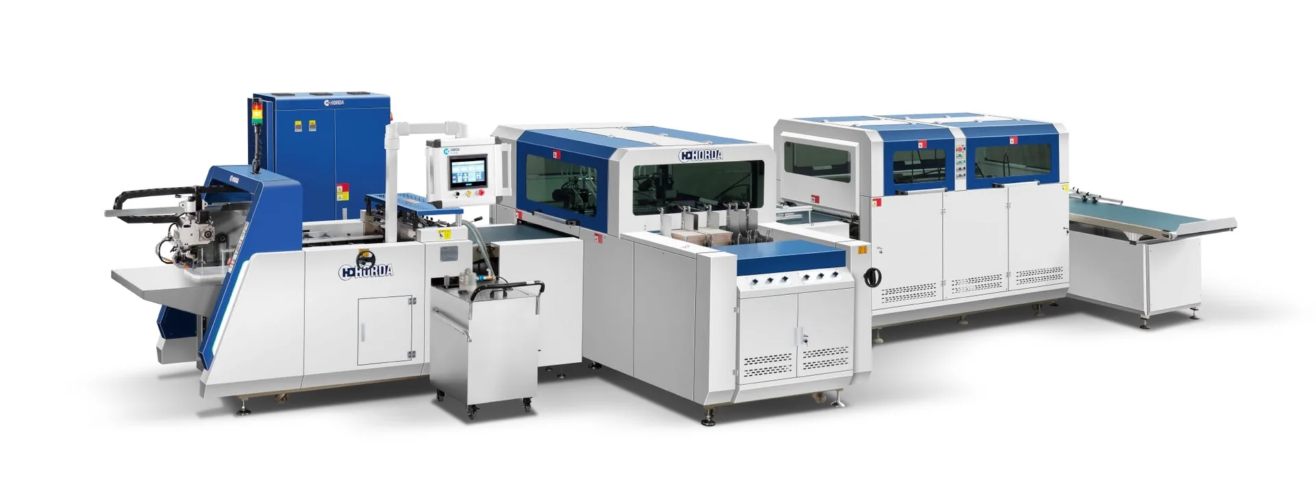
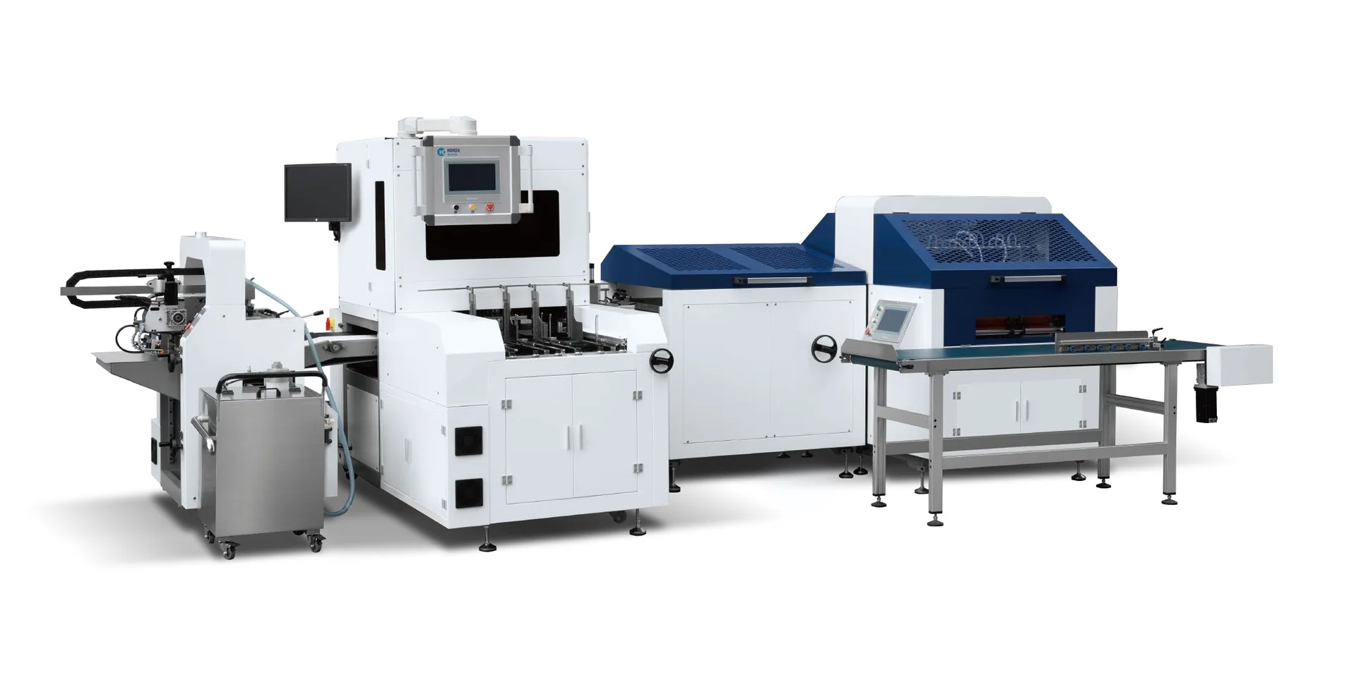
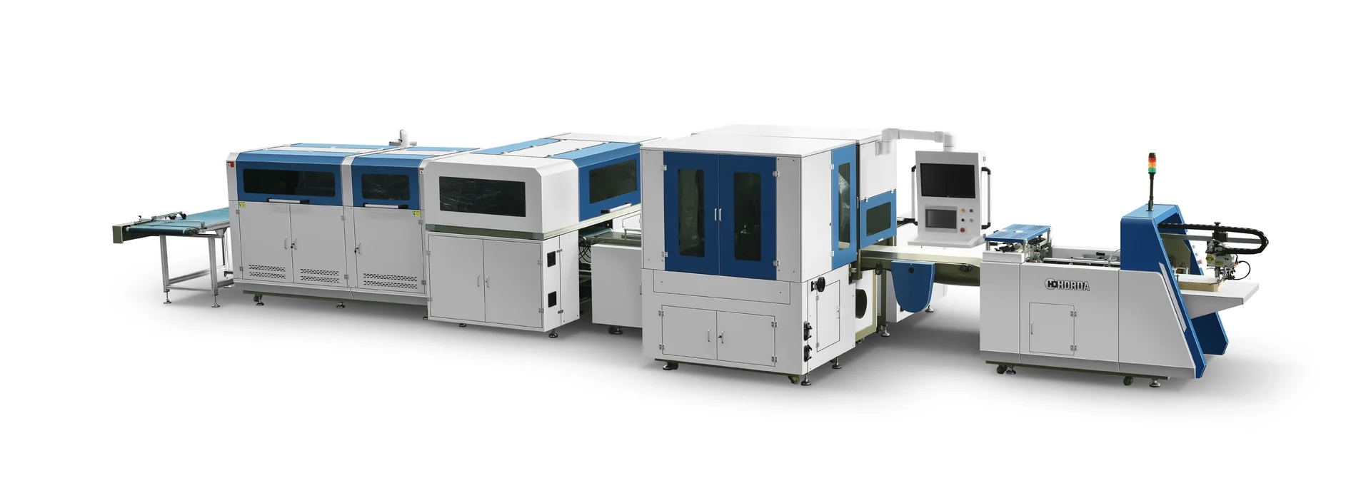
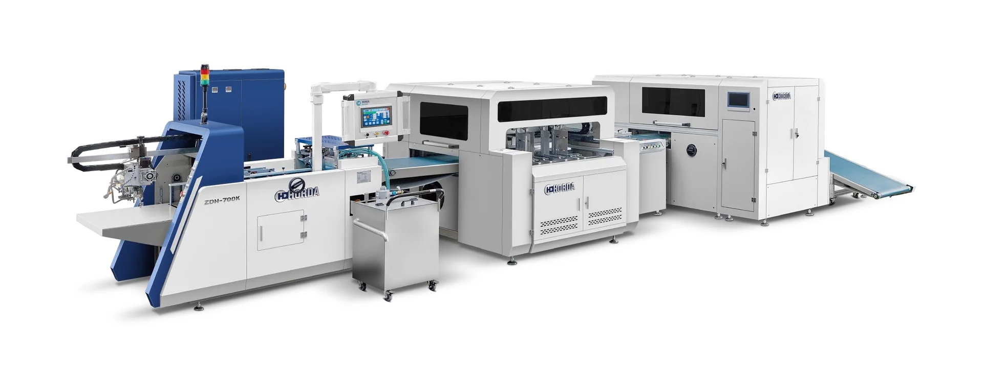
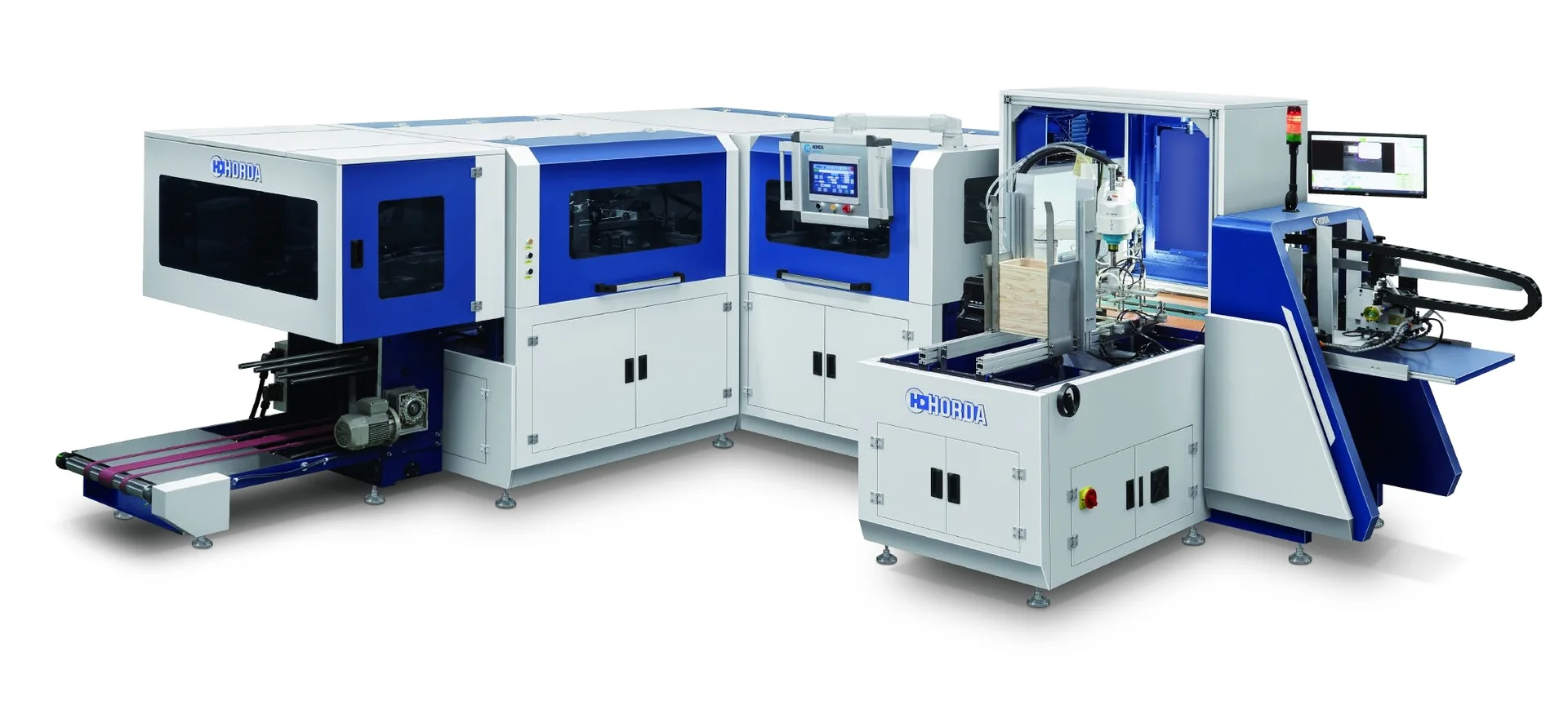
These boundaries are meaningful. HORDA’s equipment catalogue distinguishes case-making operations from inner-paper laminating and downstream box assembly. Its documented case-making and case-making/lining equipment includes functions such as board feeding, gluing, positioning, four-side wrapping, and, for relevant configurations, inner-paper application. That does not establish that every model performs all operations required for a finished necklace box.
When a visible defect is found at final inspection, it is therefore necessary to work backward through the actual production route.
Start with the incoming materials and prepared components. If board blanks already show inconsistent dimensions or flatness, later equipment may be processing an unsuitable or variable input. Adjusting the wrapping station would not, by itself, establish control over that upstream variation.
Next, examine covering preparation and positioning. A finished edge that appears offset might result from the covering sheet, the cut board, their relative placement, or a later forming operation. Comparing the parts before and after positioning helps separate these possibilities. For example, if the covering border is already offset when the board is placed, first check blank dimensions and registration. If the placement matches the approved sample but the border changes after edge folding, investigate movement or distortion during wrapping instead. These are investigation branches, not diagnoses without sample evidence.
Wrapping and corner formation introduce another set of variables. A defect that first becomes visible during edge folding deserves investigation of the local geometry, material behavior, and applicable folding conditions. Even then, the appearance of a wrinkle does not prove that the folding mechanism itself is defective.
Inner-lining and assembly operations require the same approach. If a cover was acceptable before lining but develops visible distortion afterward, the lining process and its interaction with the existing case become relevant. If the case remains acceptable until insert installation, the assembly interface deserves attention.
Three questions make this investigation more discriminating:
- Was the abnormality present before the suspected operation?
- Does it occur consistently with a particular material lot, box format, setup, or process stage?
- Which comparison between accepted and affected samples would help distinguish the competing causes?
Not every factory has inspection access at every intermediate stage. Where samples can be collected safely and practically, retaining representative stage samples can make a later investigation much more informative. Records from existing inspection points may provide similar evidence when intermediate samples are unavailable.
The key is to identify the first observable change, not simply the station where an operator discovered the finished defect.
What Causes Wrinkled Corners, Misaligned Covering and Uneven Edges?
Corner and edge defects are particularly sensitive to the interaction between material geometry and positioning. Several variables can create similar visible results, so the investigation should examine how they work together.
Corner Geometry, Turn-In and Wrapping Conditions
A wrapped rigid case requires covering material to extend around the board edges and form the intended corners. The usable covering allowance, corner geometry, board dimensions, and material behavior all influence the finished appearance.
If the covering layout leaves inadequate material for the intended turn-in, an edge or corner may not be covered as specified. In another construction, excess or uneven material around a corner may contribute to unwanted bulk or folds. Neither condition can be assessed reliably without reference to the actual cut pattern and approved construction.
Board thickness and shape also affect the geometry of the turn-in. A layout developed for one construction cannot automatically be transferred to another board or covering combination. Differences in material condition, including flatness and dimensional stability, may change how prepared components behave during converting. For a book-style or hinged case, compare the board-piece layout, spine or hinge regions, and covering extensions in the flat drawing; the closed box dimensions alone do not define these features.
Paperboard technical guidance from Holmen discusses the influence of moisture, dimensional stability, material construction, and folding-related conditions on converting performance. These principles help explain why material consistency matters, but folding-carton creasing rules are not automatically valid settings for rigid case wrapping.
For a suspected corner-geometry problem, compare the actual board dimensions, covering layout, corner cut configuration, and finished fold against the approved reference. Check whether the unwanted fold was already developing before final corner formation.
A repeatable wrinkle at one location may justify investigating that location’s geometry and process conditions. It does not, by itself, identify a particular sensor, actuator, or mechanical adjustment as faulty.
Registration, Feeding and Finished-Edge Alignment
An uneven border can result from different types of variation.
If a covering sheet or board blank was prepared to an incorrect size, the two components may not align as intended even when the positioning operation behaves consistently. If their dimensions are correct but their relative placement changes, registration during feeding or positioning becomes a more relevant investigation target.
To distinguish these conditions, compare accepted and rejected board dimensions against the same drawing revision, then compare the printed border or covering position at placement and after wrapping. Variation in the blanks points first toward preparation; changing relative placement with consistent blanks points toward feeding or registration; a difference that appears only after folding calls for a wrapping-stage check. The pattern guides investigation but still requires confirmation from the actual samples.
A printed necklace box makes registration errors particularly visible because border differences can alter the balance of decorative artwork. A plain covering may conceal some visual misalignment, but the case must still satisfy the approved dimensional and edge requirements.
Corrective action should follow the demonstrated source of variation. If the board blanks are inconsistent, repeatedly changing machine positioning will not establish a reliable material baseline. Conversely, consistent blanks do not eliminate the need to examine positioning when relative alignment varies.
Any machine-specific correction must follow the selected manufacturer’s operating and maintenance documentation. Operators should not bypass guarding or change safety-related controls during defect investigation.
Why Do Covering and Inner-Lining Defects Develop?
Not every surface defect originates during folding. Bonding behavior depends on the interaction of the covering substrate, adhesive, surface condition, application process, and subsequent handling.
This means that two boxes with similar-looking defects may require different verification methods.
Bubbles, Local Lifting and Bonding Irregularities
Raised areas beneath the covering may suggest incomplete contact, trapped air, bonding irregularities, or substrate-related distortion. Visible lifting can also reflect a mismatch between the material and adhesive system or a problem introduced after the bond was formed.
Holmen’s paperboard gluing guidance explains the importance of adhesive selection, surface wetting, applied quantity, open time, contact pressure, and bonding development. These are general converting principles, not a validated adhesive specification or setting for a particular rigid necklace box.
Their effect in a particular necklace box depends on the actual covering material, board surface, adhesive formulation, application method, and process conditions.
For example, a material change can alter bonding behavior even when the nominal adhesive application settings have not changed. A visually similar covering may have a different surface treatment or absorbency. Without confirming the material specification, treating adhesive quantity as the only possible cause would be premature.
The investigation should compare the identified materials and adhesive with their approved specifications, review available application records, and examine affected and accepted samples. Record whether the lifting was visible immediately after application, emerged after the specified setting or conditioning period, or appeared only after transfer and assembly. That timing, together with an approved sample comparison, helps separate bonding hypotheses from later material deformation or handling damage.
Where a destructive bonding check is justified, use an authorized sample and an agreed method. A published discussion of adhesive behavior does not establish the acceptable bond strength for a specific jewelry box.
Increasing adhesive application, changing pressure, or extending a process time without cause verification can introduce further variability. Exact settings must come from the selected materials, equipment instructions, and validated project process.
Inner-Lining Wrinkles, Misplacement and Edge Lifting
Inner-paper laminating introduces a different interface: the lining sheet must be applied to the intended inner surface in the required position and condition.
A displaced lining sheet may justify checking its prepared dimensions and placement. A wrinkle may involve material condition, application geometry, or local bonding behavior. An edge that lifts after lining requires a different investigation from an edge already defective before the lining stage.
Inspection should therefore establish the condition of the outer case before inner-paper application wherever the process permits.
Compare the lining dimensions with the approved layout, examine relative placement, and check whether the observed distortion coincides with application or develops later. Relevant adhesive and material records can help distinguish bonding hypotheses from positioning problems.
HORDA manufactures dedicated inner-laminating equipment as well as certain integrated case-making and inner-laminating configurations. These documented process functions help locate possible investigation stages, but they do not establish the cause of a particular lining defect or guarantee compatibility with every necklace box design.
The following matrix brings the main diagnostic distinctions together.
| Observed defect | Plausible cause families | Checks that help distinguish causes | Prevention direction after verification |
|---|---|---|---|
| Wrinkled or bulky corners | Covering geometry, material behavior, wrapping conditions | Compare corner cuts, board dimensions, covering allowance, and staged samples | Control approved geometry, material inputs, and verified forming conditions |
| Uneven edges or offset artwork | Cut-size variation, registration, component movement | Measure prepared components and compare placement before and after wrapping | Correct the confirmed preparation or positioning variable |
| Raised bubbles | Contact irregularity, possible air entrapment, substrate or bonding condition | Compare material identification, application condition, and authorized sample evidence | Validate the relevant material and application conditions |
| Lifted covering edges | Bonding irregularity, geometry, handling damage | Establish when lifting begins and inspect relevant bond or edge samples | Address the verified bonding, geometry, or handling cause |
| Warped or bowed case | Board flatness, moisture-related dimensional change, processing or assembly interaction | Compare incoming materials and case shape across stages | Control confirmed material and process contributors |
| Wrinkled or displaced inner lining | Lining dimensions, positioning, material or bonding conditions | Compare lining sheets, placement, and pre-/post-lining condition | Verify lining preparation and application controls |
| Insert or closure mismatch | Component geometry, assembly variation, interface fit | Compare outer-case dimensions and assembled components with approved samples | Correct the responsible component or assembly interface |
This matrix is a troubleshooting aid, not a fault-code table or a ranking of defect probabilities. The preventive action is appropriate only after the relevant cause has been confirmed.
Separate Outer-Case Defects from Necklace Insert, Closure and Assembly Faults
A necklace box can pass the visual checks for its outer covering and still fail as a finished package.
The insert may not sit in the intended position, the necklace may not be retained as specified, or the lid may not open and close in the approved manner. These issues affect product presentation and functional quality, but they do not necessarily originate in case making.
The first distinction is between the outer case and the components fitted to or assembled with it.
Outer-case checks can address shape, dimensions, covering quality, lining condition, and the interfaces created by those processes. Insert-related checks may involve the separately specified insert material, geometry, fitting method, and retention arrangement.
An insert that appears too large for the available interior may involve the insert itself, the finished internal opening, or the intended clearance between them. Compare the insert and internal case dimensions against the same approved drawing revision and assembled reference sample before assigning the fault. Examining only the insert—or adjusting only the case-making operation—would leave the alternative explanation unresolved.
Closure problems require similar separation. The relevant checks depend on whether the approved design uses a hinged construction, a separate lid, or another closure arrangement. A case-shape variation may affect closing behavior, while an assembly component can also create interference even when the outer case meets its specification.
A useful final inspection should therefore compare the complete assembled box against the agreed reference, including the intended product presentation where this forms part of the acceptance criteria.
The scope of automated equipment must also remain clear. HORDA’s catalogue identifies case-making, inner-laminating, and separate assembly-related processes. It does not establish that an individual case-making machine automatically produces or installs every jewelry insert or completes every type of necklace-box closure.
For a new project, the actual responsibilities of case making, lining, insert fabrication, assembly, and final quality verification should be defined before equipment suitability is assessed.
Quality Checks at Incoming, First-Article, In-Process and Final Inspection
Effective quality control should detect unsuitable inputs before they enter production, identify setup differences early, and preserve evidence when the finished product does not meet the agreed specification.
These checks serve different purposes and should not be collapsed into one final visual inspection.
Incoming inspection establishes whether materials and prepared components match the approved input conditions. Where specified, record board thickness in millimetres, covering-paper basis weight in g/m², flat blank dimensions, surface finish or coating, adhesive identity, and supplier lot references. These are different characteristics: paper basis weight is not board thickness, and nominally similar coverings may not have the same bonding surface.
First-article inspection evaluates an initial sample after setup or an approved changeover. The objective is to compare the constructed case with the relevant drawing and reference sample before relying on the setup for continuing production.
In-process inspection looks for changes after initial approval. Registration, corners, lining quality, and other relevant characteristics may be checked at defined process stages, depending on the accessible equipment and agreed control plan.
Final inspection considers the completed box as a product. This includes specified appearance requirements, relevant dimensions, and the function of the assembled insert or closure when those features form part of the order.
| Inspection stage | Main quality question | Example verification | Governing acceptance basis |
|---|---|---|---|
| Incoming materials | Are the inputs consistent with the approved specification? | Check dimensions, flatness, surface condition, material identification, and relevant records | Approved material and component specifications |
| First article | Does the setup reproduce the approved construction? | Compare covering, corners, registration, lining, and relevant dimensions with reference samples | Approved drawing, first-article sample, and project criteria |
| In-process | Has the process changed from the approved condition? | Examine defined visual and measurable characteristics and record relevant variation | Project control plan |
| Final product | Does the assembled necklace box meet appearance and functional requirements? | Inspect surface quality, geometry, insert fit, and closure operation where applicable | Customer or contractual acceptance criteria |
| Corrective-action closure | Has the verified cause been addressed without creating a new problem? | Compare evidence before and after correction and review recurrence | Approved corrective-action closure criteria |
Some inspections produce attribute results, such as the presence or absence of an unacceptable visible defect. Others produce variable measurements, such as actual component dimensions. Both can be useful, but a measured value becomes an acceptance decision only when an applicable limit or comparison basis has been defined.
Inspection frequency, sample quantity, and rejection limits should be established through the project specification and control plan. No single numerical tolerance or sampling rule applies automatically to every necklace box construction.
A production team also needs to distinguish product disposition from root-cause determination.
Inspection may demonstrate that a box does not meet an agreed requirement. It does not necessarily show why that requirement was missed. That second question requires investigation of materials, process conditions, and the stage at which variation arose.
When several possible causes remain, a cause-and-effect diagram can organize hypotheses, but it cannot by itself prove a root cause. ASQ’s 8D guidance describes subsequent cause verification, containment, corrective action, and effectiveness checks. These are general quality methods, not evidence that a particular factory uses a specified system.
Good records should identify the affected box format, relevant material lots, inspection findings, the process stage, and any approved corrective action. Photographs of defects or retained physical samples may help document comparisons where they are available and permitted.
For machine-related issues, record the observed behavior and relevant setup conditions without making unauthorized mechanical, electrical, or safety-control changes. Servicing and adjustments beyond normal approved operator procedures should be performed by qualified personnel under the applicable equipment documentation.
Prevent Repeat Defects with Verified Corrections and Clear Production Records
The immediate priority is to identify and control affected material or finished products according to the applicable quality procedure. This prevents a known quality concern from being mixed into accepted production while the investigation continues.
Next, compare the evidence from affected and acceptable samples. Use the defect location, material information, production sequence, and process observations to narrow the possible causes.
A suspected cause becomes more credible when an appropriate check can distinguish it from competing explanations. Where practical, a controlled comparison should help establish whether the proposed cause accounts for the defect rather than merely being present at the same time.
Once a cause is sufficiently verified, select a correction appropriate to the responsible stage.
If prepared board dimensions are the confirmed issue, the preventive control belongs with material or component preparation. If covering registration is demonstrated to vary, the relevant positioning and setup controls should be reviewed. If a bonding problem has been established, the material–adhesive system and its documented application conditions deserve attention.
If the problem originates during insert installation, changing a case-making setting without evidence of an outer-case contribution would not be an appropriate substitute for investigating the assembly interface.
After the correction, compare new samples with the original defect record and approved acceptance requirements. A satisfactory immediate sample is an important result, but recurrence monitoring may still be necessary to establish whether the change remains effective under relevant production conditions.
The investigation record should retain enough information to support future decisions:
- Box design or format, relevant dimensions, and drawing revision
- Board, covering, lining, and adhesive identification where applicable
- Defect description, location, and first observed process stage
- Affected sample or lot information and available production observations
- Checks performed, causes considered, and evidence supporting the conclusion
- Approved corrective action, recheck result, and recurrence follow-up
These records are also useful when discussing a recurring problem with an equipment provider. They allow the discussion to focus on the specific operation, actual materials, and observable behavior instead of a general complaint that the machine is producing defective boxes.
For a machinery evaluation, additional information may be necessary, including the complete flat-case dimensions, intended construction, material range, positioning requirements, upstream input condition, downstream assembly process, and target accepted output. These are project inputs—not proof that any particular machine will meet the requirement.
The practical objective is not to eliminate inspection or assume that automation prevents every defect. It is to establish a repeatable relationship between the observed problem, the evidence used to verify its cause, and the process control intended to prevent recurrence.
Preparing an Equipment or Process Review
If your production team is investigating recurring necklace box defects or evaluating case-making and inner-laminating equipment, prepare representative approved and affected samples, the relevant construction drawing, material details, and a record of the stage where the defect first appears.
Raymon Machinery provides an inquiry and quotation channel for HORDA-manufactured packaging equipment. These project details can be submitted for an equipment-related discussion, with exact machine suitability, process interfaces, operating requirements, and commercial responsibilities to be confirmed against the selected configuration and quotation.
A clear defect record and acceptance basis provide a more reliable starting point than requesting a machine adjustment or equipment recommendation based only on the appearance of the finished box.