

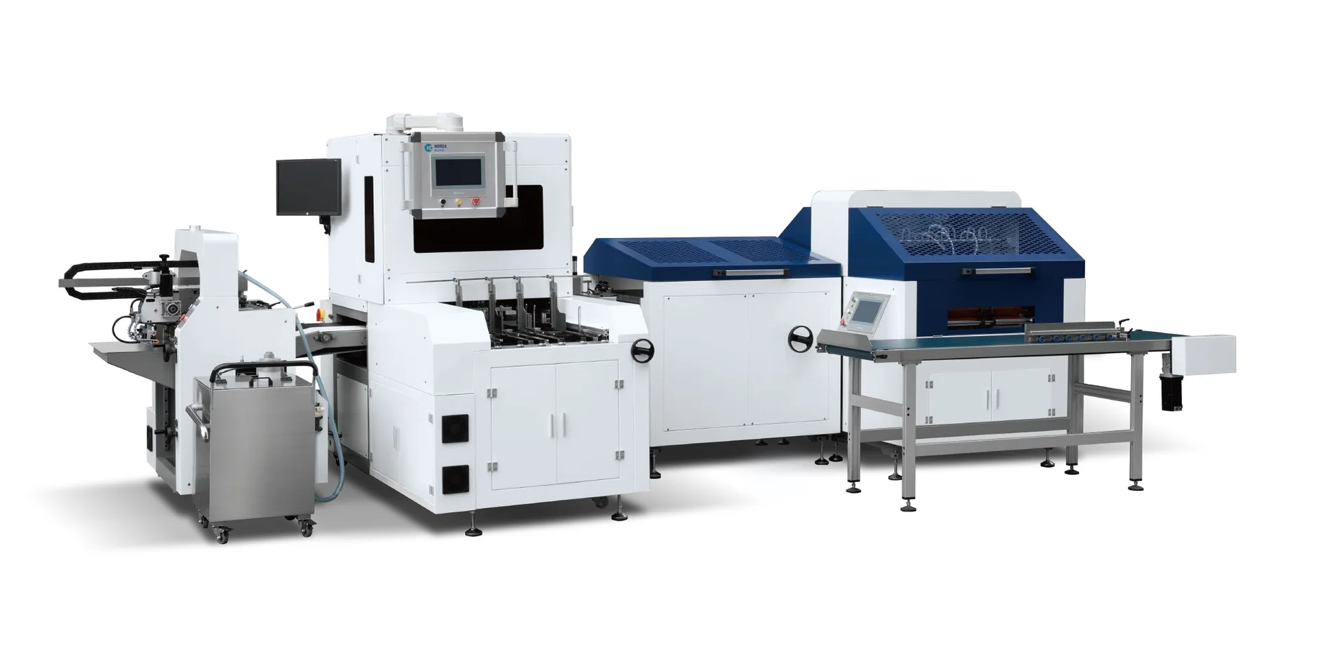
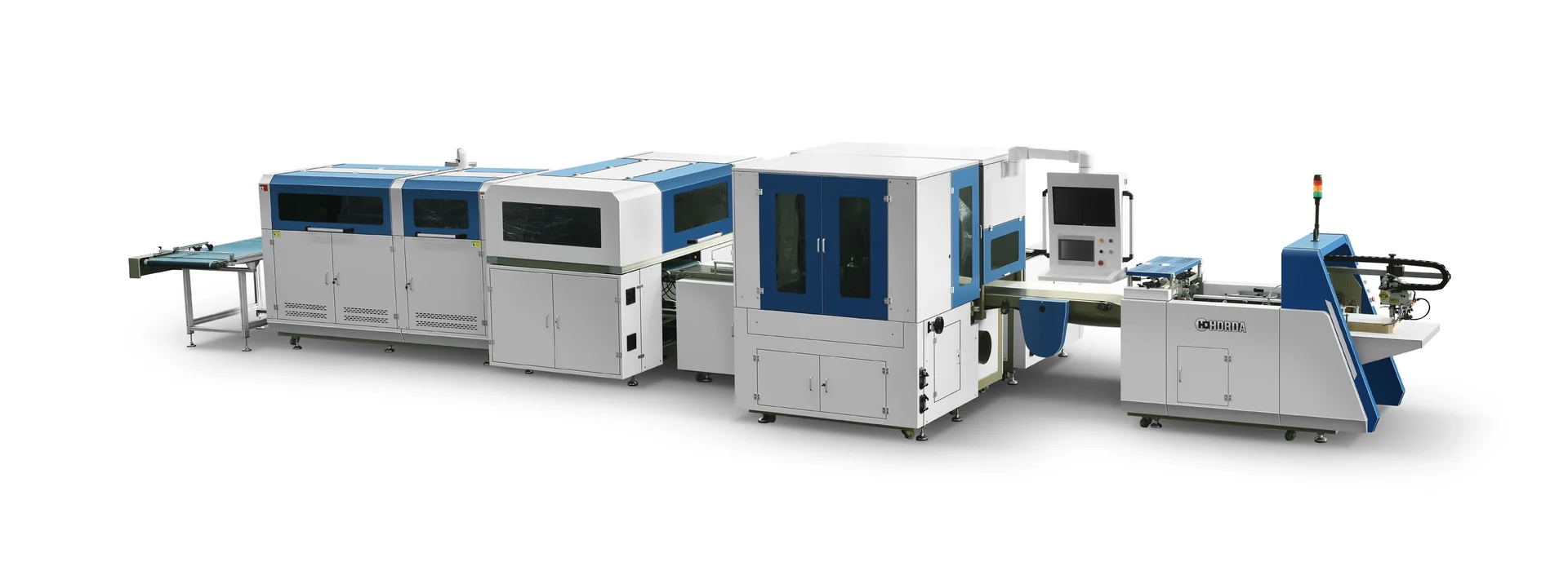
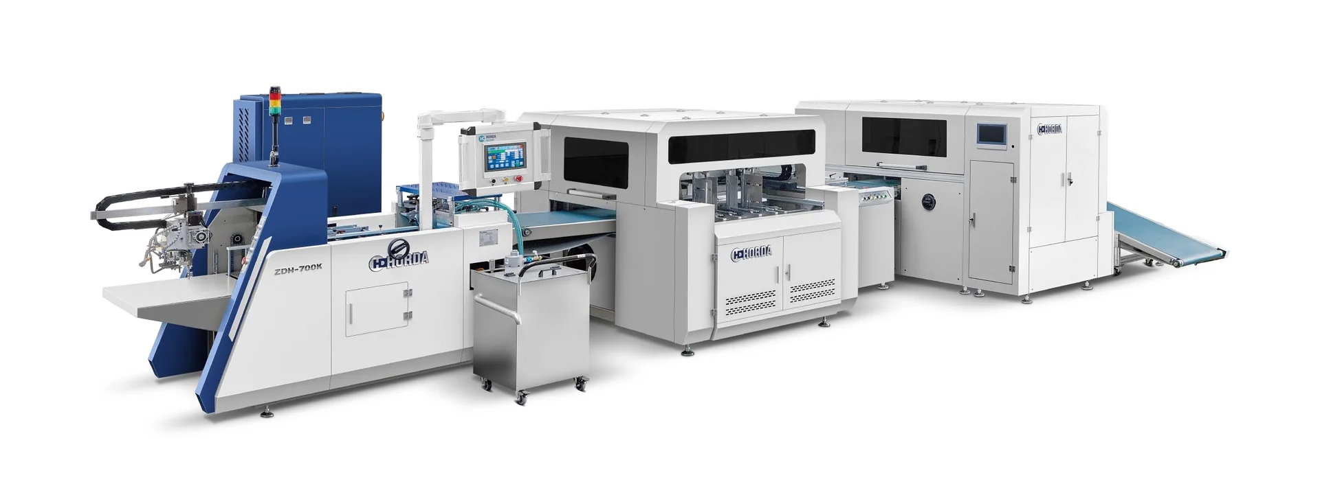
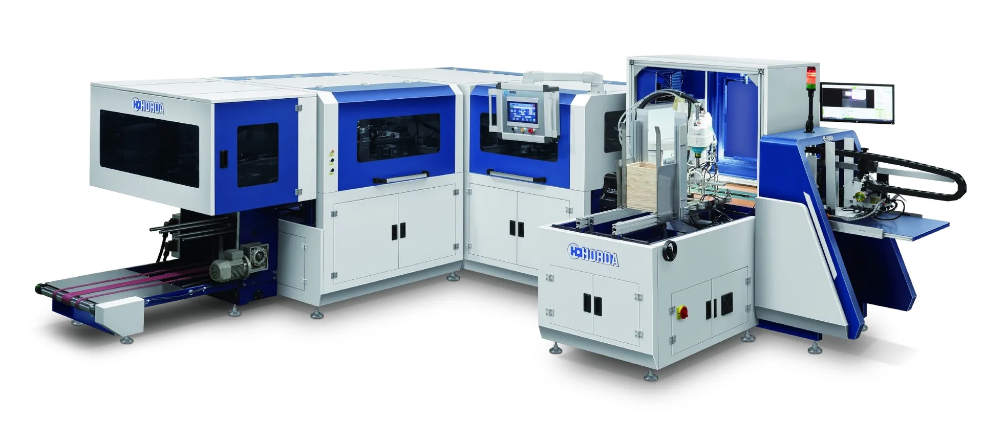
Before installing packaging machinery, buyers should confirm that the factory’s electrical supply, compressed-air system, environmental conditions and utility connection locations match the requirements of the specific machine configuration being purchased. Having sufficient nominal power, an existing air compressor or available floor space does not automatically mean a factory is ready for installation.
A reliable site utility check starts with the manufacturer’s current technical documentation. It then compares those requirements with the conditions available at the intended machine connections, taking account of auxiliary equipment, operating demand and any project-specific limitations.
For factories considering HORDA-manufactured case-making, inner-laminating, collapsible-box or frame-stretching equipment, the objective is to identify utility discrepancies before installation. This guide explains what information to request, why apparently adequate services may still be unsuitable, and how to document the remaining questions before completing a machinery RFQ or site-preparation handoff.
What Must Be Defined Before Checking Site Utilities?
The first step in utility planning is to establish exactly what equipment the factory intends to install.
A standalone case-making machine and an integrated case-making and inner-laminating line may have different equipment arrangements and utility interfaces. A machine’s published specifications may also differ from those of another model within the same product family.
The buyer therefore needs a configuration-specific equipment list. It should identify the main machine, included processing modules and any auxiliary equipment that may require electrical, pneumatic or other services. Where a production line includes several interconnected units, their individual connection arrangements must not be assumed from the specifications of an unrelated standalone machine.
HORDA’s equipment catalogue describes multiple case-making configurations, including integrated QZFM case-making and inner-laminating machines. The published specifications vary between models. The catalogue also advises buyers to request current details because machine structures and technical parameters may change.
That makes document identity important. A useful utility requirement should be traceable to the relevant model, configuration and technical document revision.
It also helps to distinguish three levels of site readiness:
- Available: The factory has the relevant infrastructure, such as electrical distribution, compressed-air piping or environmental controls.
- Compatible: The documented requirements have been compared with the conditions that the factory can provide.
- Verified: The comparison has been supported by the appropriate documents, measurements or engineering review, with unresolved discrepancies identified and addressed.
These are practical buyer-side distinctions rather than formal certification categories. Their value is that they prevent an available utility from being mistaken for a confirmed suitable connection.
Once the equipment scope is defined, the review can move from general factory capacity to the actual conditions the machinery will encounter.
Electrical Power: Match the Supply to the Machine
Electrical supply is often the first utility buyers check, but it is also easy to oversimplify. A factory may have sufficient nominal electrical capacity yet still need to resolve differences in supply configuration, connection requirements or protective arrangements.
The key distinction is between the electrical information published for a machine and the information required to design and verify its site connection.
Voltage, Phase, Frequency and Supply Connection
Request the electrical specifications for the exact machine configuration before making a decision about the factory’s supply.
Depending on the equipment and documentation, relevant information may include rated supply voltage, phase arrangement, frequency, electrical load, connection method and applicable operating or supply limitations.
The factory should compare these requirements with the supply available at the intended machine connection point.
A matching nominal voltage is useful, but it is not a complete compatibility decision. The specified phase arrangement, frequency and other electrical characteristics must also be suitable.
This is particularly important in international machinery purchases. Electrical distribution arrangements can differ between the manufacturing location and the destination factory. Buyers should not assume that a machine configured for one supply environment will automatically suit another without confirmation.
IEC 60204-1 addresses electrical equipment of machinery, including supply connections, protective arrangements and related technical documentation. Its scope provides useful engineering context, but a reference to the standard does not by itself establish that a particular machine complies with it or determine the design of an individual factory installation.
The applicable machine documentation, project requirements and qualified electrical personnel must govern the final connection decision.
Published Power Versus Actual Electrical Design Requirements
Machine catalogues often provide a power figure expressed in kilowatts. This figure can help buyers recognize differences between models, but it should not be used as a complete electrical installation specification.
The HORDA catalogue, for example, lists different published power values for different QZFM and ZFM configurations. Those entries are manufacturer-published model information; they are not measurements of the energy consumed under every operating condition.
Several additional questions affect the electrical assessment.
First, does the published figure cover the entire equipment configuration? A line may include independently powered modules or auxiliaries that are not represented by a single catalogue entry.
Second, what does the stated power figure mean in the applicable manufacturer document? Electrical power, actual energy consumption, supply current and protective-device requirements are related but are not interchangeable quantities.
Third, are there operating or starting conditions relevant to the site’s electrical design? Depending on the equipment, the characteristics of the connected loads and the factory distribution system can influence the required engineering review.
These considerations explain why simply adding together catalogue power figures from different standalone machines is not necessarily a valid way to specify an integrated production line.
A buyer should request an electrical schedule for the selected configuration and provide it to the factory’s responsible electrical engineer. That schedule, together with the applicable drawings and project requirements, should establish the basis for reviewing the intended supply connection.
The practical decision is not whether a published kW figure appears smaller than the factory’s spare capacity. It is whether the documented electrical interface can be supplied and protected appropriately at the planned installation location.
Protective Arrangements, Power Quality and Qualified Verification
Electrical compatibility also involves the suitability of protective arrangements, isolation provisions and the supply characteristics delivered to the equipment.
These matters should be determined through applicable electrical documentation and site engineering review. The machine’s published power rating alone does not establish the required breaker size, conductor dimensions, protective connection design or acceptable supply variation.
Maintenance and servicing arrangements require attention as well. For U.S. workplaces and activities within its scope, OSHA 29 CFR 1910.147 addresses hazardous-energy control, including the risk of unexpected energization or release of stored energy. It does not replace the electrical installation requirements applicable to a particular machinery project.
The buyer’s role is to make sure these questions have an identified technical owner and that the necessary machine information is available. Electrical design, installation and testing must be handled by appropriately qualified personnel under the applicable requirements.
An unresolved electrical interface should remain an open project issue until the responsible parties have established what is required.
Compressed Air: Verify Conditions at the Machine Inlet
Where a packaging machine requires external compressed air, the factory needs to confirm more than the pressure indicated on a compressor gauge.
The decisive issue is whether the system can supply the required air conditions at the machinery connection point under relevant operating demand.
Not every machine configuration has identical pneumatic requirements. Buyers should first obtain confirmation that external compressed air is required, followed by the applicable inlet pressure, air-consumption or flow information, quality requirements and connection details.
Pressure, Consumption and Flow
Pressure and airflow describe different aspects of compressed-air supply.
Pressure represents the pressure available in the system. Flow indicates the quantity of air supplied over time under a specified measurement or reference basis. Machine air consumption describes demand, which may vary with the equipment and operating condition.
A factory can have acceptable static pressure at an air connection and still experience inadequate supply conditions when equipment operates.
When air starts flowing, it encounters resistance through piping, fittings, filters, regulators and other distribution components. Pressure losses can increase with flow and other system conditions.
The result is that the pressure recorded at the compressor outlet may differ from the pressure available at a machine inlet during operation.
This distinction is important when reviewing a proposed installation. A compressor nameplate and an idle pressure reading describe only part of the supply arrangement. They do not necessarily demonstrate that the machine will receive the required air under production conditions.
The factory should compare the documented machine demand with the capability of the distribution system serving the intended connection. Where measurements are needed, the measurement location, operating condition and evaluation method should be identified.
The reference basis of any flow figure also matters. Compressed-air quantities may be quoted using different measurement conventions. Before comparing consumption with compressor or system capacity, the parties should confirm that the units and reference conditions are consistent.
Distribution Losses and Simultaneous Demand
A shared compressed-air network introduces another variable: other equipment may consume air at the same time.
A compressor and distribution system that appear adequate when only one production machine is operating may provide different conditions when multiple machines demand air simultaneously.
This is not necessarily a compressor-capacity problem alone. The result can depend on distribution restrictions, pressure losses, system controls, storage and the pattern of demand.
The U.S. Department of Energy’s Improving Compressed Air System Performance discusses system demand and the effects of distribution and pressure losses. That engineering framework supports evaluating the complete supply path rather than relying solely on compressor outlet conditions.
A packaging machinery buyer should therefore ask whether the intended connection is part of a shared air network and whether relevant simultaneous demand has been considered.
If the factory has only a compressor rating, but no information about the air available at the proposed machine inlet, the correct conclusion is that point-of-use compatibility remains unverified—not that the machine is necessarily unsuitable.
The next step may involve a distribution-system assessment, an appropriate operating-condition measurement or additional manufacturer data.
Air Quality, Dryness and Filtration
Compressed-air suitability also depends on quality where the selected equipment specifies it.
Moisture, particles or oil contamination can be relevant to pneumatic components and processes, depending on the actual system and equipment requirements.
ISO 8573-1 provides a classification framework for compressed-air purity in relation to particles, water and oil. However, the standard does not automatically assign an air-purity requirement to every packaging machine.
Buyers should check whether the actual equipment documentation specifies filtration, drying, oil-content limitations or an air-quality class.
When such requirements are absent from the available documents, the buyer should request clarification rather than select an arbitrary class or air-treatment configuration.
The objective is to match the air supply with the documented machine requirement—not to add specifications that the project has not established.
Temperature and Humidity: Separate Environment from Process
Electrical and compressed-air requirements often appear as technical connection data. Temperature and humidity require a different review because they can involve both the machine and the materials being processed.
This is especially relevant to packaging operations using paperboard, covering paper and adhesives.
Machine Ambient Conditions Versus Process Temperature
The temperature of the workshop is not necessarily the same as the temperature required at an individual machine component or process station.
Ambient temperature describes the environment surrounding the equipment. Process temperature refers to a particular operation, material or controlled component.
The distinction matters because a machine may contain local heating functions without requiring the entire factory to maintain the same temperature.
For example, the HORDA catalogue describes a temperature-controlled paper-conveying feature and an insulated glue tank in its discussion of relevant case-making equipment. These are descriptions of machine components, not universal ambient-temperature requirements.
They also do not establish a suitable operating temperature for every adhesive formulation.
Buyers should therefore request machine environmental limits and applicable process-temperature requirements separately. If an adhesive is involved, the relevant supplier documentation may define additional preparation or working conditions.
A temperature value from one machine component, adhesive or production process should not be transferred to another without a supported technical basis.
Paperboard, Covering Paper and Adhesive Conditions
Paperboard and paper-based materials can change condition as they absorb or release moisture.
Research on humidity effects in press-formed paperboard packaging has demonstrated relationships between moisture conditions and dimensional stability in the studied materials and forming process. That finding supports considering material conditioning during packaging production, but it does not establish universal environmental limits for hardcover case making, inner laminating or HORDA equipment.
The practical question for a packaging factory is how its intended materials will behave under the expected storage and production conditions.
Consider a planned case-making operation using paperboard, covering paper and adhesive. The machine’s mechanical settings are only one part of the production environment. Material moisture condition and adhesive working requirements may also need attention, depending on the selected materials and processes.
A successful trial using one substrate condition does not automatically prove equivalent results with another substrate, adhesive or seasonal environment.
For a useful site review, the buyer can record the intended board and covering materials, the relevant supplier technical information, and the workshop conditions under which they are expected to be stored and processed.
Any specific acceptable temperature or humidity range must come from applicable machine, material, adhesive or project documentation.
Workshop Dust, Moisture, Ventilation and Local Heat
The local surroundings of the machine may differ from the conditions indicated by a general workshop measurement.
Nearby heat sources, moisture-producing operations, dust-generating processes or ventilation arrangements can affect the environment experienced by the equipment or packaging materials.
A buyer should identify these conditions when they are relevant to the proposed installation and compare them with the applicable documentation.
However, the presence of a gluing operation does not automatically establish a particular ventilation rate, and the presence of dust does not justify assigning an unsupported filtration system or machinery protection rating.
Those decisions require the actual process, equipment and applicable workplace requirements.
This environmental review is most useful when it identifies conditions that need confirmation, rather than when it attempts to prescribe a universal factory climate for every packaging machine.
Site Interfaces: Connection Locations, Auxiliary Units and Access
Even when the available utilities meet the intended technical requirements, their physical locations can create installation problems.
A factory may have suitable electrical and compressed-air infrastructure, but the nearest connection points may not align with the selected machine arrangement.
This is why published equipment dimensions should not be confused with a complete installation layout.
The machine envelope identifies the approximate physical extent of the equipment under the documented configuration. An installation must also consider relevant operating activities, material movement, auxiliary units, utility connections and service access.
Integrated machinery can make this distinction more important because the complete arrangement may contain several processing sections rather than one compact machine.
For example, an integrated case-making and inner-laminating arrangement may include feeding, gluing, case forming, transfer and lining-related sections. Its actual connection and access requirements must be established from the configuration-specific documentation rather than inferred from the process description alone.
A useful site-interface review compares the current machinery layout with the factory’s proposed installation position. It should identify the relevant connection locations, the routes by which services will reach them, and any possible interference with normal material handling or necessary access.
The buyer should distinguish:
- Machine envelope: The dimensions published for the relevant equipment configuration.
- Operating area: Space needed for the applicable production and material-handling activities.
- Utility connection area: Positions and routes required for the machine’s relevant service interfaces.
- Maintenance access: Space needed for applicable inspection and service tasks as defined by manufacturer documentation and safety requirements.
No universal clearance, floor-loading or anchoring requirement should be assumed from this general framework. Those values require the selected equipment’s current drawings and project-specific engineering review.
Unloading, rigging and international transport involve related but separate planning responsibilities. The focus here is the condition of the installed machine’s utility interfaces.
The Site Utility Verification Matrix
Once the technical requirements and factory conditions have been identified, buyers need a way to record the comparison.
A useful checklist should not ask only whether electricity, compressed air or temperature control is available. It should show what the machine requires, what the factory can provide, how the comparison was verified and what remains unresolved.
The following matrix is a recommended buyer-side planning tool. It is not a HORDA official acceptance form, a certification record or a substitute for project-specific engineering approval.
| Utility / interface | Machine-side information required | Factory-side verification | Evidence or action to record |
|---|---|---|---|
| Electrical supply | Voltage, phase, frequency and connection data for the selected configuration | Supply characteristics at the intended connection | Source document, comparison result and any mismatch |
| Electrical demand and protection | Applicable electrical schedule, loads and relevant documents | Qualified review of site supply and protective arrangements | Review status and responsible party |
| Compressed-air pressure | Required inlet pressure, where external air is needed | Connection-point conditions under relevant demand | Measurement or assessment basis |
| Compressed-air flow | Required consumption/flow and its reference basis | Available delivery under applicable operating conditions | Basis comparison and outstanding questions |
| Compressed-air quality | Specified filtration or purity requirements, if applicable | Relevant air-treatment and quality information | Confirmed requirement or clarification needed |
| Temperature and humidity | Applicable machine/environmental limits | Intended operating conditions | Documented conditions and identified gaps |
| Material/process conditions | Relevant board, paper and adhesive requirements | Material storage and intended process conditions | Supplier data and technical review status |
| Connection locations | Machine and auxiliary-interface drawings | Proposed position and utility routing | Layout conflict or confirmed arrangement |
| Documentation and responsibility | Current technical revisions and agreed project scope | Assigned reviewers and outstanding items | Open, reviewed, verified or approved status |
The most valuable part of this matrix is not the number of completed rows. It is the visibility of the difference between documented requirements and actual site capability.
How Buyers Should Use the Matrix
Begin with the equipment scope. Record the exact model, selected modules and auxiliary equipment that form part of the proposed installation.
Next, obtain the relevant current documentation. Each important machine-side requirement should have an identifiable source rather than an unsupported estimate.
The factory then supplies its corresponding information. This may include existing technical records, site drawings or measurements taken under appropriate conditions.
For each requirement, record the exact machine configuration and document revision, the required value and units, the site value or drawing used for comparison, and the measurement point and operating condition where relevant. Record the discrepancy, the party assigned to resolve it, the next action and the review status. If a value is missing, mark it as not yet verified rather than treating the utility as suitable. Labels such as “open”, “verified” and “awaiting project approval” are suggested tracking states, not HORDA acceptance categories.
For example, if a compressor nameplate is available but the delivered air conditions at the intended machine inlet have not been assessed, the compressed-air entry should remain open. It should not be marked acceptable merely because the compressor’s published capacity appears sufficient.
The same principle applies to electrical supply. If only the machine’s catalogue power figure is known, the factory may still need the full electrical interface information before a qualified reviewer can assess the connection.
Finally, assign each unresolved item to the appropriate responsible party. A useful record should distinguish technical confirmation from contractual acceptance and should preserve the document or measurement basis behind the decision.
This process makes the matrix usable for procurement discussions and site preparation without representing it as an official inspection or acceptance certificate.
Closing Utility Gaps Before Installation
A site-utility review is most valuable when its open items are resolved before they affect equipment configuration, factory preparation or installation responsibilities.
The buyer should first make sure that the proposed machine scope is unambiguous. If the quotation concerns an integrated line, the supporting utility documentation should correspond to that line rather than to unrelated standalone equipment.
The factory then needs to confirm which required conditions it can already provide and which may need further technical assessment.
The outstanding information can be organized into five practical groups:
- Equipment identification: Exact machine model, modules, auxiliaries and current document revisions.
- Utility requirements: Applicable electrical supply, compressed-air, environmental and physical connection data.
- Site information: Relevant factory supply characteristics, intended installation location, operating conditions and available drawings.
- Unresolved discrepancies: Missing information, incompatibilities or requirements still awaiting technical review.
- Responsibility and confirmation: The party expected to resolve each issue and the applicable written confirmation or approval procedure.
These items help the buyer distinguish an incomplete information package from a genuine incompatibility.
For example, an unknown pneumatic flow requirement does not demonstrate that the factory’s air system is inadequate. It means the comparison cannot yet be completed. The next appropriate action is to obtain the missing requirement or arrange a suitable technical review.
Similarly, an equipment layout that has not been checked against utility connection locations is not necessarily unusable. It remains unverified until the relevant drawings and site arrangement have been compared.
The responsibility for performing the work should not be assumed from the existence of an equipment quotation. The manufacturer, equipment inquiry channel, factory engineering team and external contractors may have different roles, depending on the actual agreement.
Any commitments relating to utility preparation, connection work, installation, commissioning or formal acceptance should therefore be confirmed in the relevant purchase and project documents.
Electrical and pneumatic installation decisions must follow the applicable technical and safety requirements. This buyer-oriented guide is not an electrical design manual, a hazardous-energy procedure or proof of regulatory conformity.
For buyers evaluating HORDA-manufactured equipment through Raymon Machinery, a useful inquiry package includes the proposed equipment configuration, the intended installation location, known electrical and compressed-air conditions, relevant workshop constraints and the open questions identified by the review.
Prepare your machinery RFQ: Share the proposed machine configuration, factory utility information, site layout constraints and outstanding interface questions through Raymon Machinery’s quotation or contact channel. The applicable machine specifications and any installation or service responsibilities must be confirmed through current manufacturer documentation and the written project agreement.
A factory is not utility-ready simply because services are present in the building. Readiness depends on the selected machine’s requirements, the conditions actually available where it will operate, and the evidence supporting the necessary engineering and project confirmations.